E. remote options - input/out descriptions – SARGENT AL - Alarmed Exit User Manual
Page 2
2
A7251C
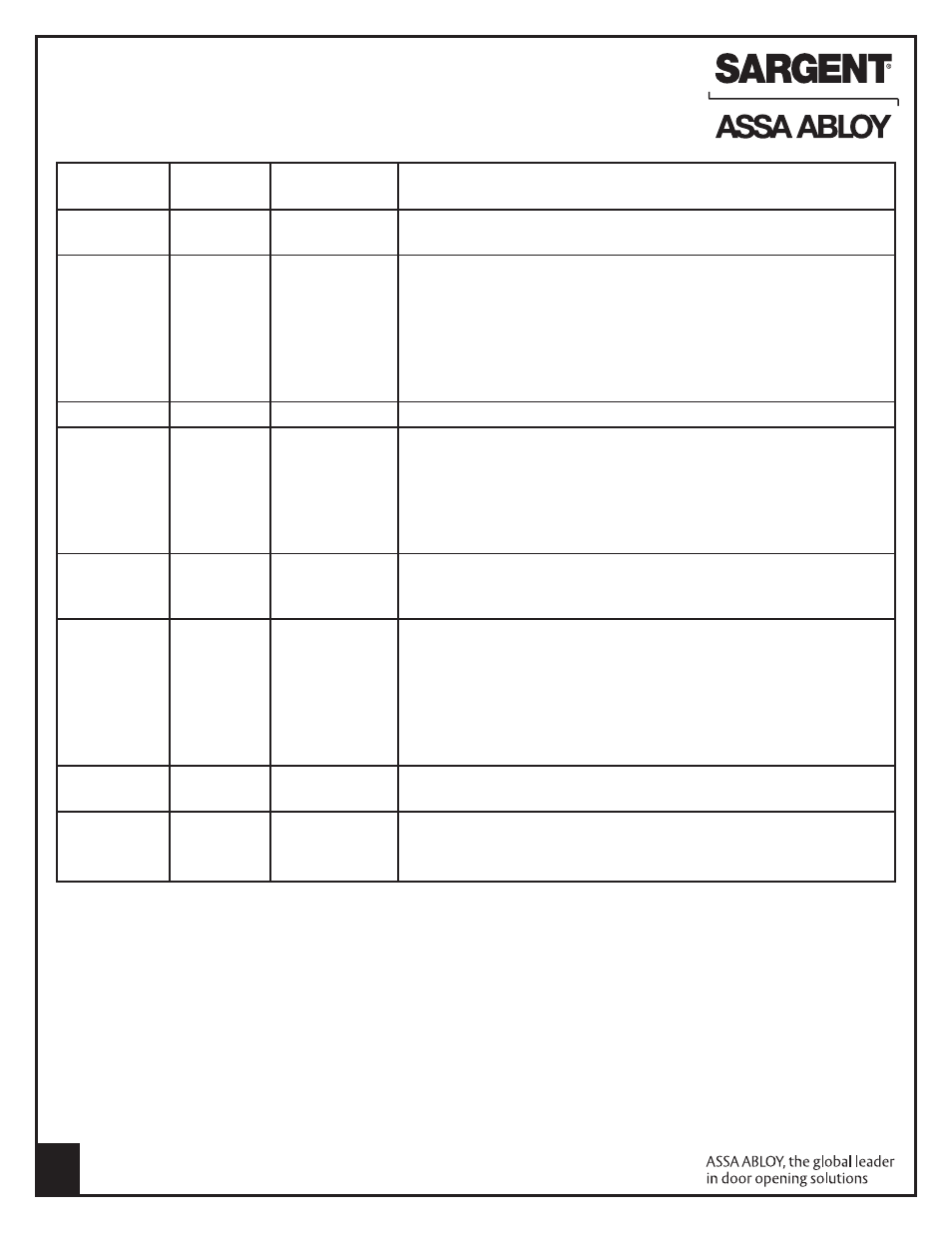
E. Remote Options - Input/Out Descriptions
Note: Refer to instruction A7224B REX/Passage and Automatic Alarm Reset Tables
Pigtail
Circuit Board
Remote
Connector
Connector
Option
Description
Black (-9v), 8-1
J1 - 2
Remote Power
Allows unit to be connected to 9vdc power supply Model 3267
Red (+9v), 8-2
J1 - 1
(Input)
Refer to 3267 instructions A7477
White, 8-3
J4 - 1
REX
Wired to normally open external switch or relay contact.
Orange, 8-5
J4 - 2
(Request to exit)
Momentary switch closure shunts rail, allows egress for selectable
(Input)
time of 7, 10, 15 or 20 seconds (see Passage Table), then rail rearms.
Maintained switch closure shunts rail, allows egress until switch opens,
then rail rearms after selectable passage delay of 7, 10, 15 or 20
seconds or portion of selected passage delay
Note: LED flashes yellow during switch closure
Green, 8-4
Earth Ground
Use to connect rail to 3267 power supply earth ground terminal
Blue (C), 8-6
J3 - 2
Remote Monitor With unit armed, depressing push bar shall sound the alarm
Brown (NO), 8-7
J3 - 3
(Output Relay)
and the output relay will change state until the unit is disarmed with a
Yellow (NC), 8-8
J3 - 1
cylinder key, remote reset, or automatically reset after selectable
time delay of 2, 5 or 10 minutes (see Automatic Alarm Reset Table).
Note: Dip Switch SW-2 position 6 must be ON (Refer to SW-2 Table).
SW-2 position 6 OFF disables output relay
Violet, 4-1
J4 - 3
Tamper/Door Status With door closed, wire to door status switch open contacts. With rail armed,
Grey, 4-2
J4 - 4
(Input)
the alarm will sound when door is opened (switch is electrically closed).
Alarm will sound until reset with cylinder key or automatic alarm reset time
Pink, 4-3
J4 - 5
Remote Reset/Arm Wired to normally open external switch or relay contact. When rail is
Tan, 4-4
J4 - 6
(Input)
violated (alarm on), the rail alarm is reset and rail is rearmed as follows:
Momentary switch closure resets alarm, then rail is rearmed after
selected passage time of 7, 10, 15 or 20 sec (see Passage Table).
Maintained switch closure resets alarm/keeps rail disarmed.
When switch is reopened, the rail rearms after selected passage time
Note: LED remains OFF. Recommended for remotely disarming rail long term
Red (+), J2 - 1
Battery
Connects 9vdc battery to circuit board
Black(-), J2 - 2
(Input)
Gray, J2 - 3
To Internal
Wired normally open and mechanically held (maintained) closed.
Black,J2 - 4
Rail Switch
Alarm activates when switch is electrically opened (when push
(Input)
bar is depressed)
Copyright © 2004, 2006, 2008, 2009, 2012, Sargent Manufacturing Company, an ASSA ABLOY Group company. All rights reserved.
Reproduction in whole or in part without the express written permission of Sargent Manufacturing Company is prohibited.