Seventh, Eighth, Ninth – SARGENT HC8700 Hurricane Code Surface Vertical Rod Exit Device User Manual
Page 6: Adjust top & bottom rods, Attach bottom strikes & case
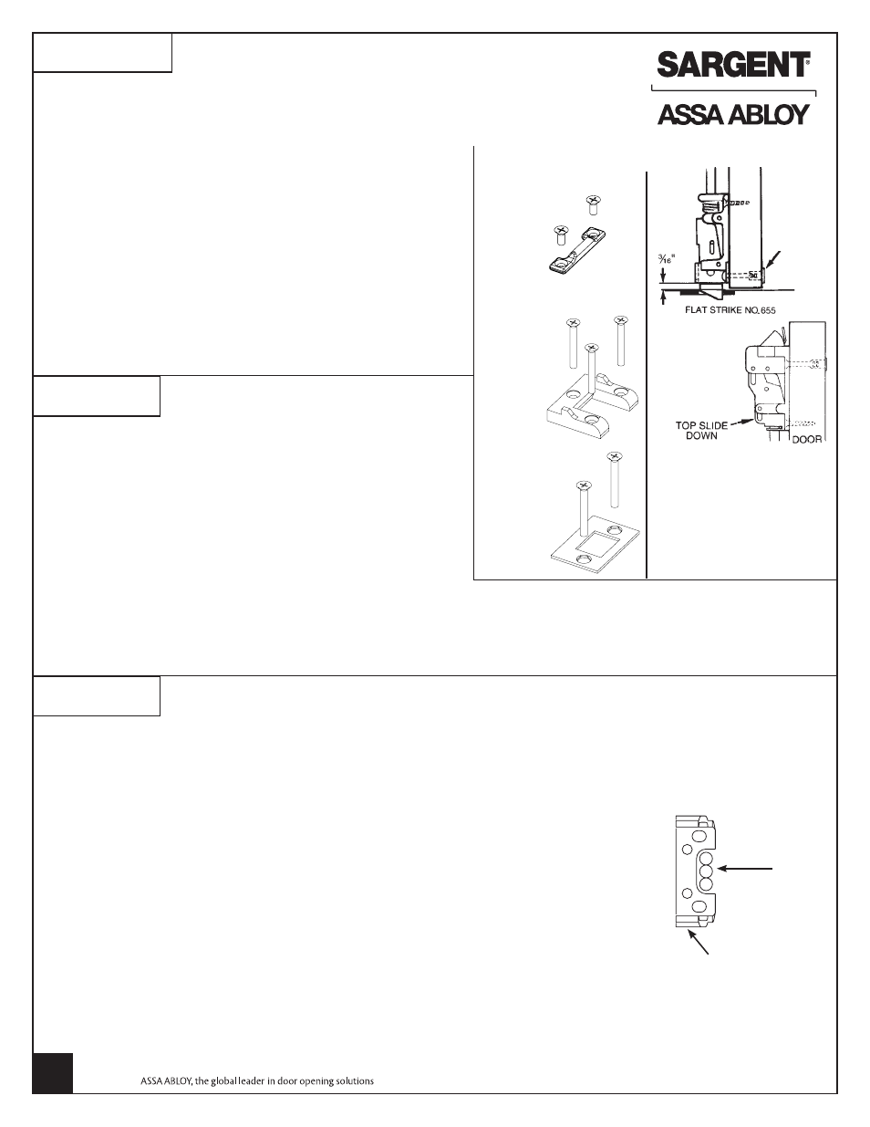
SEVENTH
ATTACH STRIKES (Continued)
ELECTRICAL FUNCTION PREFIXES
To access wire channel in door, drill three (3), 1/4" holes in “U”
shaped cutout of mounting bracket.
59- Prefix
Connect switch cable to cable coming from the front of the rail.
Refer to instruction book A7690 for additional wire connections and operating instructions.
AL- Prefix
There are no external wire connections unless used with 546 wiring harness.
Refer to instruction book A7224 for operating instructions.
55- Prefix
Refer to instruction sheet A6808 for wire connections.
56- Prefix
Refer to instruction sheet A6876 for wire connections.
57- Prefix
Refer to instruction sheet A6810 for wire connections and operating instructions.
58- Prefix
Refer to instruction sheet A6835 for wire connections.
1/4” Holes
Mounting
bracket
BOTTOM STRIKES
For thresholds with integral strikes, skip to next step.
For surface applied strikes 624 or 653:
WITH DOOR CLOSED:
1. Transfer vertical centerline to floor or threshold and mark.
2. Engage bottom strike with latchbolt and center on line marked.
3. Mark mounting holes.
4. Drill holes for required fasteners.
5. Mount strike with fasteners provided.
6. Tighten screws securely.
For mortised strikes: 636 or 655
Follow steps above. Mark mounting holes
and outline of strike.
653 Bottom Strike
Alternate Strike for
HC-, 12-, 14-
624 Bottom Strike
(Panic)
1. Fine adjustment is made by turning rod into top and bottom
case to shorten or out of top and bottom case to lengthen.
2. Rough adjustment is made by changing hole used for
adjustment pin.
3. Top Rod Adjustments: Push on door as you push on the rail
assembly. As soon as the door opens, release rail, the top bolt
should be in the hold back position. If not, extend top bolt.
Note: the top bolt must go into hold back position prior to the
door opening.
EIGHTH
ADJUST TOP & BOTTOM RODS
NINTH
2-ISOMETRIC
(2) #12-24 screws
(2) 1/4-20
screws
(3)
#1/4-20
screws
655 Bottom Strike
(HC, 12- & 14-)
4. Bottom Bolt Adjustments: Extend bottom bolt for maximum engagement with the bottom strike. When the top bolt
is in, hold back, it also holds the bottom bolt in the retracted position. Always verify that when the bottom bolt is in
the retracted position, that the bolt clears the finish floor by at least 1/8" through the swing of the door.
Be sure that both top and bottom latch bolts are adjusted for maximum engagement
Copyright © 2009-2011, Sargent Manufacturing Company, an ASSA ABLOY Group company.
All rights reserved. Reproduction in whole or in part without the express written permission
of Sargent Manufacturing Company is prohibited.
A6701L
11-30-11
Steel Screws
and Mortise
Nut
Note: Use two (2) No. 10
steel screws and mortise
nuts (when provided) in
the position illustrated in
the bottom chase. Steel
mortise nuts are twin
knurled for identification.
ATTACH BOTTOM STRIKES & CASE
6