Fifth 4 fourth, Apply rail assembly, Mount top case – SARGENT HC8700 Hurricane Code Surface Vertical Rod Exit Device User Manual
Page 4
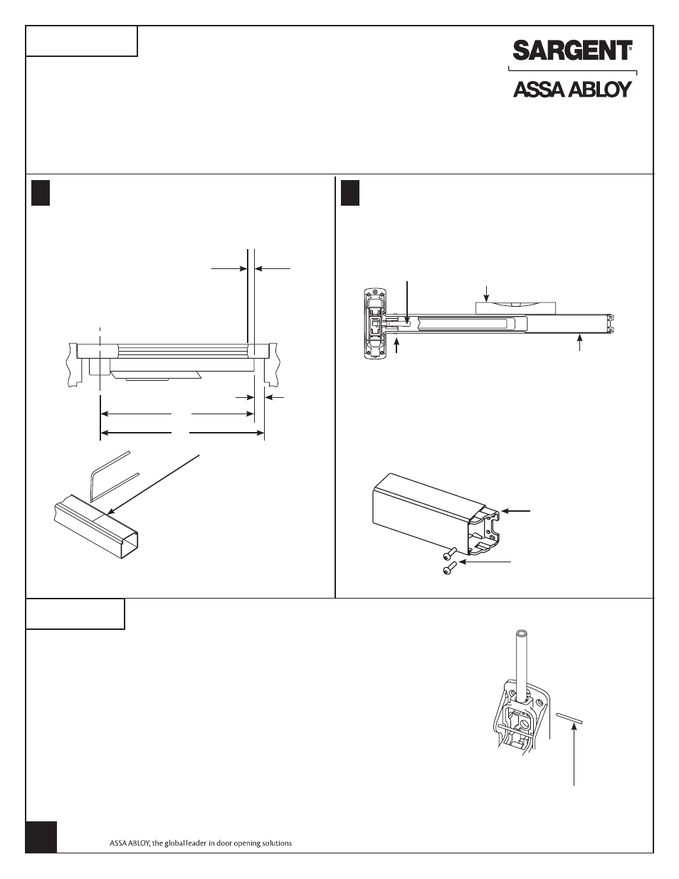
APPLY RAIL ASSEMBLY
Check box label.
The following prefixes are provided “factory cut” to size: AL-, 56-, 57-, 58- and 59-.
If cutting is required, continue with step “A”.
If cutting is
not required, proceed to step “B”.
A
Determine rail length dimension “X” by subtract-
ing 1-3/4" from dimension “Y”.
B
TOP VIEW OF EXIT DEVICE
For doors with stile, the rail
must overlap stile by 1/2" or
more
Vertical reference line
(CL of chassis)
1-3/4" min.
“X”
Cut off mark
1. Dog push rail and cut off
at mark.
2. Cut must be straight.
3. For (43-) flush end cap use
cutting guide provided.
4. Remove sharp edges with file.
1. Slide rail assembly over lift arm and onto chassis.
2. Attach rail assembly to chassis with two (2)
#8-32 truss head machine screws.
NOTE: DO NOT tighten screws.
3. Level rail and position mounting plate tight
against rail and attach to door with two (2) #10
round head screws.
4. Tighten all screws securely.
Lift arm
Level
Rail assembly
Rail mounting screw
(2 places) #8-32 x 3/8 ph.
truss head machine screw
Mounting
plate
Mounting plate
screws (#10-24 x
3/4" ph. rd. head
machine screw)
1. Verify rail is not dogged.
2. Screw rod into top case until finger tight.
3. Slide top rod into main slide – do
not pin in place.
4. Attach top case as located in second step.
Through-bolts required and supplied for fire rated top cases on wood doors.
5. Unscrew top rod until the center hole is aligned with the hole in the main slide.
6. Insert rod adjustment pin.
Rod adjustment pin
MOUNT TOP CASE
FIFTH
4
FOURTH
Copyright © 2009-2011, Sargent Manufacturing Company, an ASSA ABLOY Group company.
All rights reserved. Reproduction in whole or in part without the express written permission
of Sargent Manufacturing Company is prohibited.
A6701L
11-30-11