Backset, Install 7u93, 6305 template – SARGENT 7 Line User Manual
Page 4
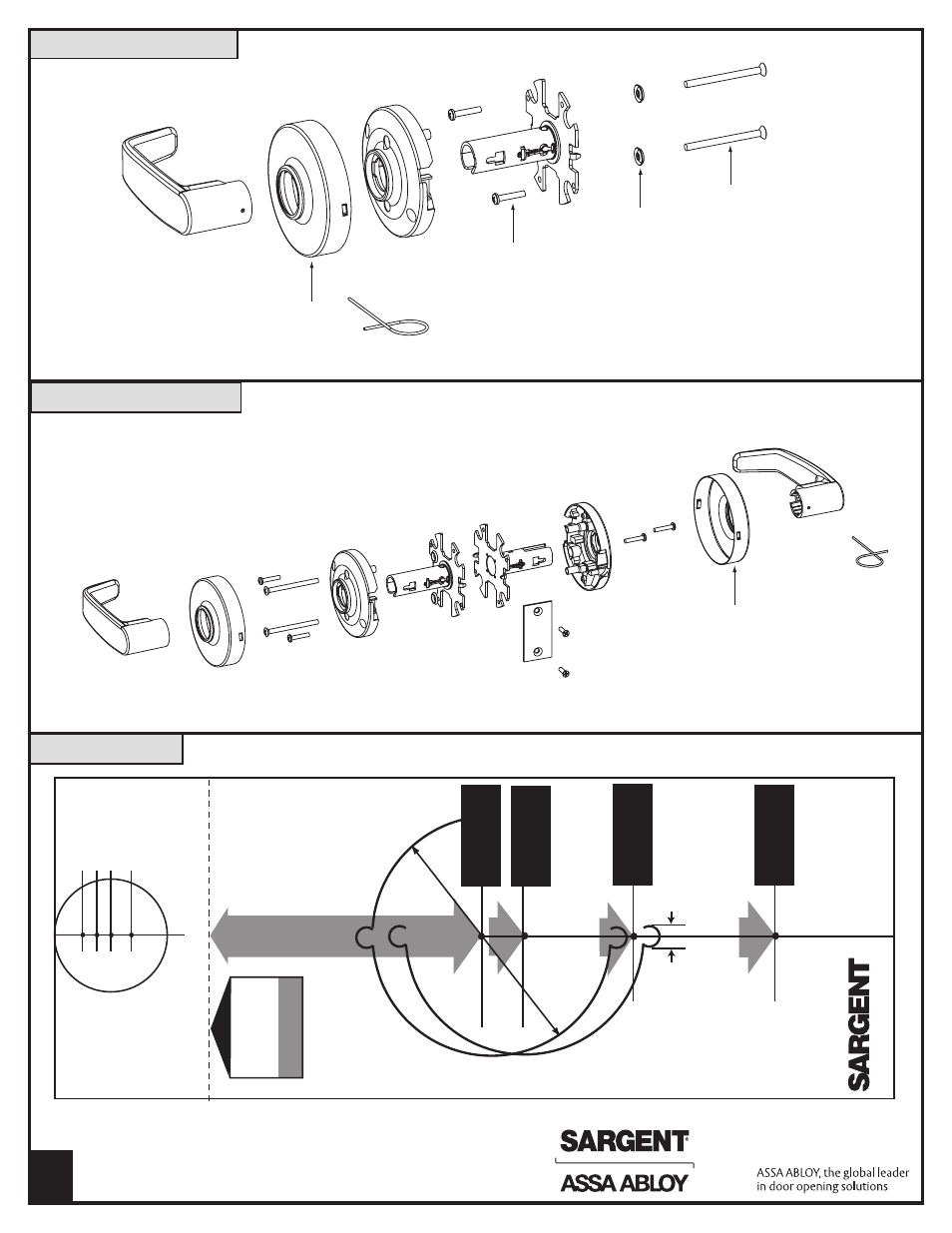
Install 7U94/7U94-2
4
Install 7U93
Through-bolt
Screws (2)
# 8 - 32 x 2-1/8"
Cup
Washers
(2)
Self-tapping
screws (2)
# 6 x 3/4"
Scalp- twist
to secure
on to rose
Scalp- twist
to secure
on to rose
Determine corr
ect backset and
door thickness - then place template on door and mark for holes.
High edge of beveled door
Bor
e 2-1/8"
hole thru door
Cut out to fit lock fr
ont, as
shown
Bor
e 1" hole
thru into first hole (this hole must be center
ed in
door edge and must be parallel to sides).
38" from floor
recommended height
Swivel fr
ont
latch std. for flat and beveled doors
Centerline for strike scr
ews
and fr
ont scr
ews
To prep door for loc
k
To mortise frame for strike
Cut out jamb for strike
Stop
Lock
Strike
Guar
dbolt stops on strike
when door is closed.
See reverse side
When strike box is not used, r
ecess in jamb
must be deep enough to allow latchbolt to extend its full fr
ee length.
Locate strike scr
ews at
1/2 the door thickness measur
ed fr
om stop.
5/32 (4mm)
1-1/8 (29mm)
2-1/4 (57mm)
1
2
3
4
Note
- Consult factory
for corr
ect template
information for 38-2, 93, 94, and 94-2 functions
2-1/4" (57mm)
2" (51mm) 1-3/4" (44mm)
1-3/8" (35mm)
Fold her
e on
high edge of beveled door
Drill 1" (25mm) hole at center of door thickness
5/32" Dia. (15mm)
A6305F
IMPORT
ANT
SEE BACK FOR DIRECTIONS
BACKSET
Standar
d
6 line
Standar
d
7, 8 &
9
line
2-3/8" Backset (60mm) Nominal
2-3/4" Backset (70mm) Nominal
3-3/4" Backset (95mm) Nominal
2-1/8" Dia.
5" Backset (127mm) Nominal
®
A7240D
Copyright © 2013, Sargent Manufacturing Company, an ASSA ABLOY Group
company. All rights reserved. Reproduction in whole or in part without the
express written permission of Sargent Manufacturing Company is prohibited.
6305 Template