2a 3 1 2 – SARGENT 7 Line User Manual
Page 2
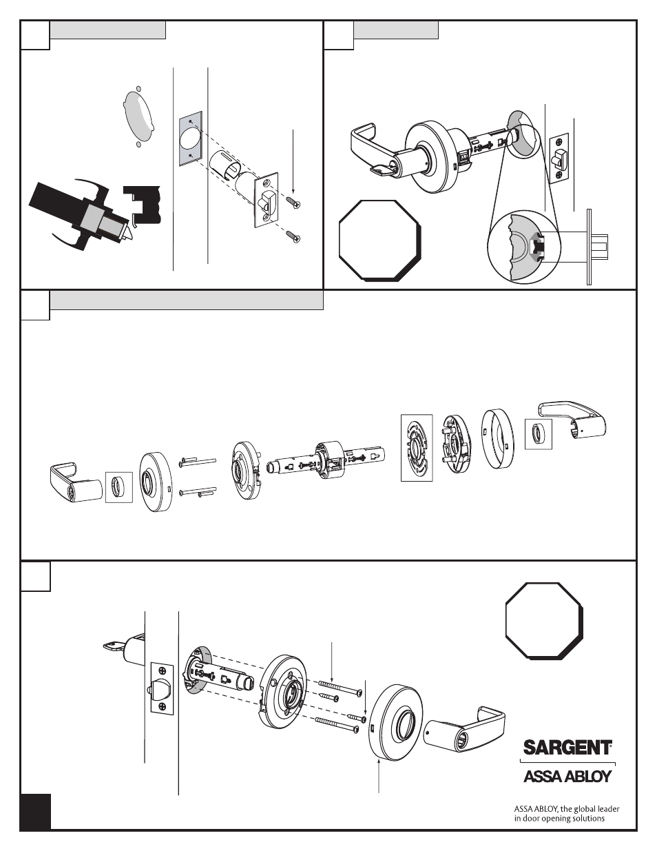
Preset Lock
Latch Installation
Door
frame
2A
3
1
2
Install latch and
sleeve (1" prep)
loosely; tighten
screws after step #3
Screws (2)
#8-32 x 3/4"
Outside
of Door
Door thickness – 1-3/4" (44mm) - centered
• See step 2A for adjusting for
1-3/8" (35mm) thick doors
2
• Disassemble — outside lever (see page 3), scalp,
outside rose assembly, outside mounting plate and spacer
• Reassemble — Add 3 parts (2 bushings and slim mounting plate)
as shown below in boxed areas
•
IMPORTANT: To center lock in door, rotate threaded mounting
plate on completely
Adjustment for 1-3/8" (35mm) Thick Door
Through-bolt screws
(2) #8-32 x 2-1/8"
Self-tapping screws
(2) # 6 x 3/4"
Scalp- twist to
secure on to rose
IMPORTANT
Lockbody
must be
centered
in the door
Test
for proper
operation
before
closing
door
•
IMPORTANT: Self-tapping screws MUST be installed
A7240D
Copyright © 2013, Sargent Manufacturing Company, an ASSA ABLOY Group
company. All rights reserved. Reproduction in whole or in part without the
express written permission of Sargent Manufacturing Company is prohibited.
- Profile Series v.G1.5 Cylindrical Locks (26 pages)
- Profile Series Mortise Locks (1 page)
- Profile Series Mortise Locks (14 pages)
- Profile Series v.G1.5 Cylindrical Locks (12 pages)
- Profile Series v.G1.5 Cylindrical Locks (2 pages)
- Profile Series v.G1.5 Exit Devices (16 pages)
- Profile Series v.G1.5 Exit Devices (26 pages)
- Profile Series Mortise Locks (1 page)
- Profile Series Mortise Locks (8 pages)
- Profile Series Mortise Locks (2 pages)
- Keypad Cylindrical Locks (26 pages)
- Keypad Mortise Locks (23 pages)
- Keypad Exit Devices (26 pages)
- Profile Series v.G1.5 Mortise Locks (20 pages)
- Profile Series v.G1.5 Mortise Locks (22 pages)
- Profile Series v.G1.5 Mortise Locks (12 pages)
- Profile Series Exit Devices (28 pages)
- Profile Series v.G1.5 Cylindrical Locks (18 pages)
- Profile Series v.G1.5 Cylindrical Locks (12 pages)
- Passport 1000 PG Exit Devices (28 pages)
- Passport 1000 PG Mortise Locks (22 pages)
- Passport 1000 PG Cylindrical Locks (22 pages)
- Passport 1000 P2 Mortise Lock (1 page)
- Profile Series v.S2 Mortise Locks (2 pages)
- Profile Series v.S2 Mortise Locks (2 pages)
- IN100 Mortise Locks (20 pages)
- 11 Line Lever Lock (1 page)
- 11 Line Lever Lock (4 pages)
- 10 Line Cylindrical Lock (2 pages)
- 10 Line Cylindrical Lock (1 page)
- 10 Line Cylindrical Lock (1 page)
- 10 Line Cylindrical Lock (2 pages)
- 10 Line Cylindrical Lock (4 pages)
- DL Series Tubular Lock (3 pages)
- RDL Tubular Lock with Simpli Roseless Trim (2 pages)
- 6500 Line (2 pages)
- GX Series (3 Line) (2 pages)
- GX Series (3 Line) (4 pages)
- 9898 Reversible Rim (2 pages)
- 8200 Ecoflex Electrified Mortise Lock (8 pages)
- 9200 High Security Locksets (1 page)
- 50- Prefix/185S Kit Secured Indicator Rose (2 pages)
- 3P8225 Levers (4 pages)
- 8200 Lever Lock (4 pages)