Door preparation, Function specific instructions - sleeve assembly, Lock disassembly – SARGENT 11 Line Lever Lock User Manual
Page 2: Latchset installation
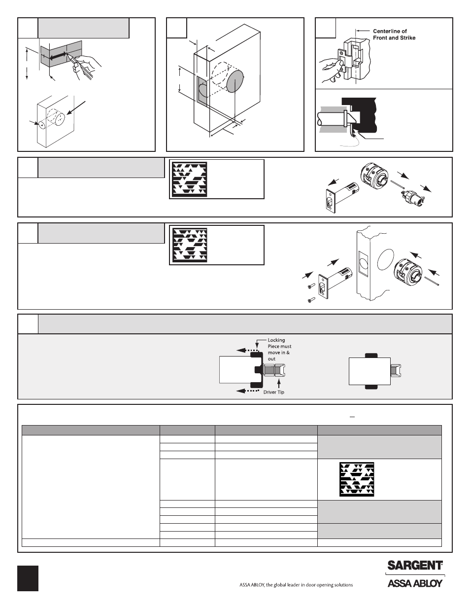
Door Preparation
2
4
1
3
OUTSIDE
INSIDE
2
3
1
1. Unthread collar and remove OUTSIDE sleeve
2. Remove aligning pin from bearing assembly
3. Separate latch from bearing assembly
Hold door open with door stop
1. Insert bearing assembly
2. Insert latch assembly
3.
Insert aligning pin from secure side (outside)
of door
4. Install latch plate screws. Do not tighten
completely until lock installation is finished
Inside
Inside
Outside
Outside
Function Specific Instructions - Sleeve Assembly
• Mark centerline on jamb
• Mark outline of strike
• Fold template on
door and mark
hole centers
2-1/8" Hole
• Cut recess for latch bolt
• Install strike; secure with
two screws
IMPORTANT
Guardbolt stops on strike
when door is closed
2
3
• Cut rectangular front recess
DESIRED BACKSET
5/32" DEEP
RECESS
1-1/8"
2-1/4"
1"
STRIKE
See Specific Instructions Per Function. Identify Function On Box (Example: 11G05)
For functions not shown proceed to step 7
6
• Bore 2-1/8"
• Bore 1" hole
2
Copyright © 2013 SARGENT Manufacturing. All rights reserved. Reproduction in whole or in
part without the express written permission of SARGENT Manufacturing is prohibited.
A7469K
1
Lock Disassembly
4
Latchset Installation
5
38"
2-1/8"
1"
High edge of
beveled door
Finished
floor
1/8"
GUARDBOLT
Scan to see a video of
this installation step.
Scan to see a video of
this installation step.
Scan to see a video of
this installation step.
Outside Sleeve
Function Number
Function Description
Inside Sleeve
Align driver tips matching the painted sections
04
Storeroom/Closet
Follow Step 7
05
Entrance/Office
16
Classroom Security/Apartment
17
Utility/Asylum
24
Entry
Follow Step 7
44
Service Station
65
Privacy/Bathroom
38
Classroom Security
Follow Step 7
54
Dormitory
See A7608B
50
Hotel/Motel
See A7608B
Note: Outside sleeve has collar
attached
IMPORTANT:
Sleeves with colored driver tips require that the slotted cam be
rotated allowing the spring loaded locking piece to move freely in and out of
the outside sleeve
Driver Tips with red markings must match up before assembling lock
PLEASE NOTE
— Some driver tips have two color markings for function
identification
11G54 - green
11U65 - blue
11G24 - yellow
11G05 - only red
Outside
Sleeve
"Spring loaded"
position
Outside
Sleeve
Outside
Sleeve
Outside
Sleeve
"Spring loaded"
position
Outside
Sleeve
Outside
Sleeve