Cb a, Assembly – Viking Pump TSM153: N-R 333/4333 User Manual
Page 7
c
B
a
SECTION TSM 153
ISSUE
D
PAGE 7 OF 16
ASSEMBLY
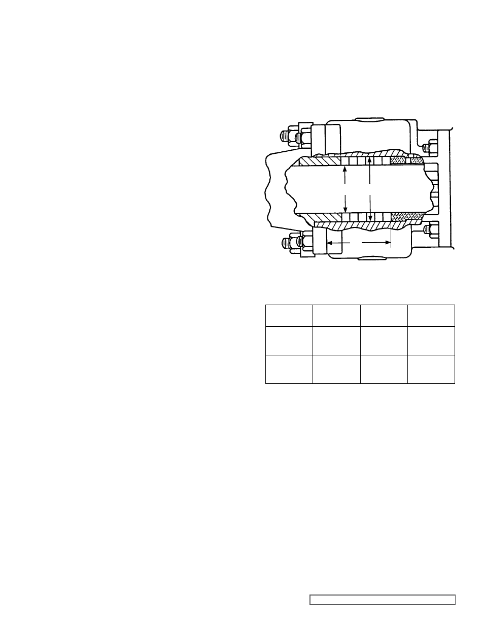
FIgURE 8
STUFFINg BOX DIMENSIONS
1. Install rotor bearing sleeve and gasket on casing. Coat
both sides of gasket with thread sealant (pipe dope) and
quickly install gasket and rotor bearing sleeve on casing.
Place a support under rotor bearing sleeve to prevent
casing and rotor bearing sleeve from tilting down while
rotor is being installed.
2. Check casing to be sure drain plug has been removed.
3. Carefully check shaft, remove any burrs or rough surfaces
to avoid damaging rotor bearing sleeve bushing while
installing rotor and shaft into casing. Coat inner diameter
of rotor bearing sleeve bushing and shaft with a thin coat
of non-detergent SAE 30 weight oil.
Support weight of rotor with a hoist. A cable sling can be
used around shaft, or around rotor teeth, to carry weight
of part while being assembled into casing.
Place end of rotor shaft through casing, into bushing
slowly turn rotor from right to left while pushing into
casing. When shaft first protrudes from stuffing box,
stop pushing. Check to see if large diameter of shaft has
protruded far enough into rotor bearing sleeve to permit
installing packing rings.
Use packing suitable for liquid being pumped. Lubricate
packing rings with oil, grease or graphite to aid assembly.
Packing ring joints should be staggered from one side
of shaft to the other. A length of pipe will help set each
packing ring.
4. Place packing gland and inner end cap (spanner wrench
holes on side next to packing gland) with lip seal (lip
facing away from packing gland) over end of shaft.
5. Push rotor far into casing as far as it will go.
6. Prior to installing head, coat casing face with thread
sealant (pipe dope) and place a new .015” head gasket
on mounting studs. Coat dry side of gasket with thread
sealant (pipe dope) and prepare to mount head on idler
assembly.
Pump head and casing were marked before disassembly
to ensure proper reassembly. If not, be sure idler pin,
which is offset in pump head, is positioned toward and
equal distance between port connections to allow for
proper flow of liquid through pump. Place head on pump,
slightly tilting top of head away from casing until crescent
enters inside diameter of rotor. Rotate idler on idler pin
until idler teeth mesh with rotor teeth. Raise head until
face of head is parallel with face of casing and work into
position. Care must be taken to avoid damaging head
gasket. Fasten head to casing with nuts and tighten
evenly.
If relief valve was not removed from head, install on
head with adjusting screw cap pointed toward such port.
Refer to Figure 2, page 2. For PRESSURE RELIEF
INSTRUCTIONS, REFER TO PAgE 14.
7. Push rotor back against head.
8. Install drain plug in casing.
9. Pack pump with new packing. Refer to Figure 8. Models
N and R333 have 6 rings of packing.
10. Install thrust bearing housing on end of rotor ring sleeve
and tighten nuts and capscrews securely. It is not
necessary to use gasket between these parts.
PUMP
MODEL
A
(INCH)
B
(INCH)
C
(INCH)
N333
4.625”
4.688”
3.438”
R333
4.625”
4.688”
3.438”