Assembly – Viking Pump TSM153: N-R 333/4333 User Manual
Page 12
SECTION TSM 153
ISSUE
D
PAGE 12 OF 16
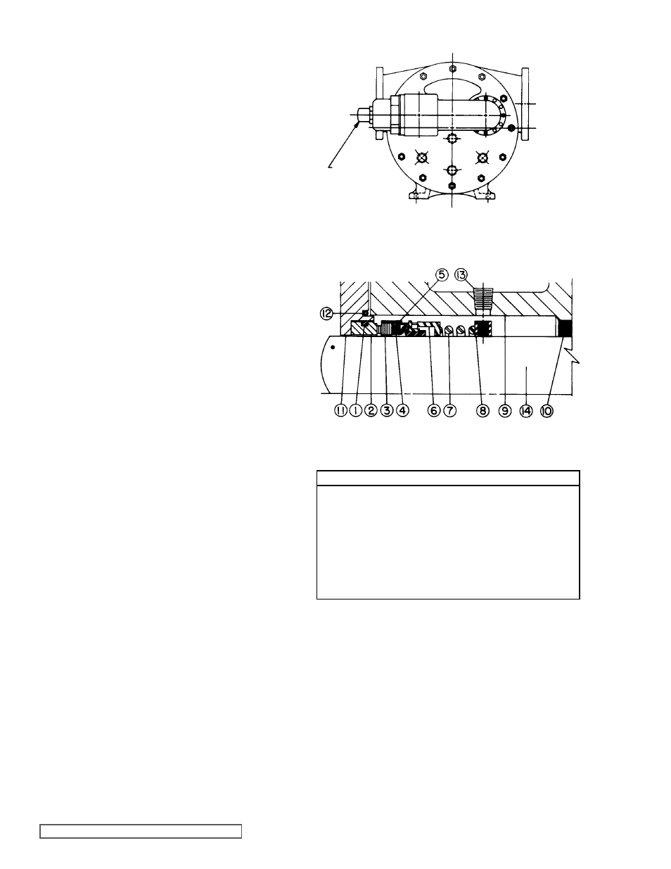
INLET
OR
SUCTION
OUTLET
OR
SUCTION
RELIEF
VALVE
ADJUSTINg
SCREW
ASSEMBLY
FIgURE 15
FIgURE 16
MECHANICAL SEAL
Standard Mechanical Seal (Synthetic Rubber Bellows Type)
Prepare all parts for reassembly ahead of time. Pack roller
bearings with multi-purpose grease, NLGI # 2 and have all
new gaskets on hand.
Be especially careful to keep mechanical seal parts clean.
Minute dirt particles especially on seal fences, will cause
leakage. Never touch seal fences with anything except clean
hands or clean cloth.
Once rotating position of mechanical seal is installed on
rotor shaft, it is necessary to assemble parts as quickly as
possible to ensure seal does not stick to shaft in the wrong
axial position. The seal should be expected to stick to shaft
after several minutes setting time.
1. Deburr threads on rotor shaft with a fine file and place a
layer of tape over threads to protect rotor bearing sleeve
bushing during assembly. Gently radius leading edge of
largest diameter on shaft (.03 inch is sufficient to aid in
seal installation). Smooth radius with crocus cloth. Polish
rotor shaft from leading edge through mechanical seal
area with crocus cloth. Any scratches left on shaft in seal
area will provide leakage paths under mechanical seal.
2. Install rotor bearing sleeve and gasket on casing. Coat
both sides of gasket with thread sealant (pipe dope) and
quickly install gasket and rotor bearing on casing. Place
a support under rotor bearing sleeve to prevent casing
and rotor bearing sleeve from tilting down while rotor is
being installed.
3. Check casing to be sure drain plug has been removed.
4. Coat inner diameter of rotor bearing sleeve bushing with
a thin coat of non-detergent SAE30 weight oil.
Support weight of rotor with a hoist. A cable sling can be
used around shaft, or around rotor teeth, to carry weight
of part while being assembled into casing.
Place end of rotor shaft through casing into bushing. Do
not allow any portion of shaft to strike bushing. A carbon
graphite bushing can be severely damaged if struck.
Slowly turn rotor from right to left while pushing into
casing. Push rotor as far into casing as it will go.
5. Prior to installing head, coat casing face with thread
sealant (pipe dope) and place new .015 inch head gasket
on mounting studs. Coat dry side of gasket with thread
sealant (pipe dope) and prepare to mount the head and
idler assembly.
6. Pump head and casing were marked before disassembly
to ensure proper reassembly. If not, be sure idler pin,
which is off set in pump head, is positioned toward an
equal distance between port connections to allow for an
even flow of liquid through pump.
Place head on pump, slightly tilting top of head back
away from casing until crescent enters inside diameter of
rotor. Rotate idler on idler pin until idler teeth mesh with
rotor teeth. Raise head until face of head is parallel with
face of casing and then work into position. Care must be
taken to avoid damaging head gasket. Fasten head to
casing with head nuts and tighten evenly.
If relief valve was removed from head, install on head
with adjusting screw cap pointed toward suction port.
Refer to figure 19 for PRESSURE RELIEF VALVE
INSTRUCTIONS, page 14.
LIST OF PARTS
1. O-Ring Seat Gasket
8. Set Collar with Setscrews
2. Stationary Seat
9. Rotor Bearing Sleeve
3. Rotating Face (Washer) 10. Rotor Bearing Sleeve Bushing
4. Bellows
11. Seal Holder Plate
5. Metal Parts
(Retainer, drive band)
12. O-Ring Gasket for seal
holder plate
6. Spring Adapter
13. Pipe Plug
7. Spring
14. Shaft
Note:
Items 1 through 7 comprise the complete mechanical seal.
7. Push rotor back against head.
8. Install drain plug in casing.
9. Wipe shaft clean in seal area and thoroughly coat with
non-detergent SAE 30 weight oil.
Before installing parts contained in the mechanical seal,
refer to figure 20 to become familiar with part name and
location in rotor bearing sleeve.
10. Install set collar on shaft in rotor bearing sleeve directly
under tapped access hole. Center line of collar set
screws (5/16” socket head) must line up with center line
of access hole. Rotate shaft and tighten all setscrews.
Replace pipe plug in seal access hole.