Viking Pump TSM153: N-R 333/4333 User Manual
Page 11
SECTION TSM 153
ISSUE
D
PAGE 11 OF 16
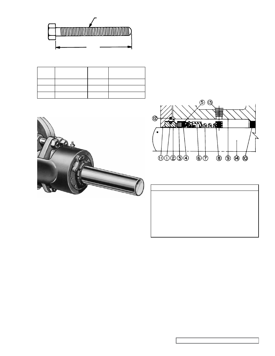
LIST OF PARTS
1. O-Ring Seat Gasket
8. Set Collar with Setscrews
2. Stationary Seat
9. Rotor Bearing Sleeve
3. Rotating Face (Washer) 10. Rotor Bearing Sleeve Bushing
4. Bellows
11. Seal Holder Plate
5. Metal Parts
(Retainer, drive band)
12. O-Ring Gasket for seal
holder plate
6. Spring Adapter
13. Pipe Plug
7. Spring
14. Shaft
Note:
Items 1 through 7 comprise the complete mechanical seal.
FIgURE 13
FIgURE 14
MECHANICAL SEAL
13. Clean all parts thoroughly and examine for damage. If
lipseal replacement is needed, press in end cap with lip
facing end of shaft. Check idler bushing and idler pin,
replace if necessary.
If idler pin is to be replaced, oil grove on pin must be
installed facing center of crescent on head.
If idler bushing is to be replaced, a press must be used to
remove old bushing and install new. Bushing position after
being pressed in should be flush with face of idler. For
carbon graphite idler bushing,
refer to INSTALLATION
OF CARBON gRAPHITE BUSHINgS, page 14.
14. Wash bearing in clean solvent. Blow out bearings with
compressed air. Do not allow bearings to spin; turn
bearing slowly by hand. Spinning bearings will damage
race and rollers. Make sure bearings are clean, then
lubricate with non-detergent SAE 30 weight oil and check
for roughness. Roughness can be determined by turning
outer race by hand.
CAUTION: do not intermix inner and
outer races for roller bearings.
15. Examine casing for wear. Check condition of casing
at seal area (surface between suction and discharge
ports). If surface is in good condition, casing need
not be replaced. When making major repairs, such as
replacement of a rotor, it is usually considered advisable
to install a new head and idler. When making minor
repairs, when only an idler bushing and idler pin are
required, other new parts are usually not necessary.
16. Inspect the mechanical seal for wear or damage. Refer
to figure 14 for mechanical seal list of parts. In general, if
the pump has been operated long enough to exhibit other
worn parts, it is likely the seal will have to be replaced.
Replacing individual seal parts is not recommended, i.e.,
a used seal washer will not perform satisfactorily when
run against a new stationary seat.
THREAD SIZE
a
MINIMUM LENgTH OF JACK SCREWS
FIgURE 12
PUMP
SIZE
NO. SCREWS
USED
a
THREAD SIZE
(INCH)
N
2
4.00
0.50” - 13 NC
R
2
4.50
0.63” - 11 NC
P
3
5.00
0.50” - 13 NC