Viking Pump TSM153: N-R 333/4333 User Manual
Page 6
SECTION TSM 153
ISSUE
D
PAGE 6 OF 16
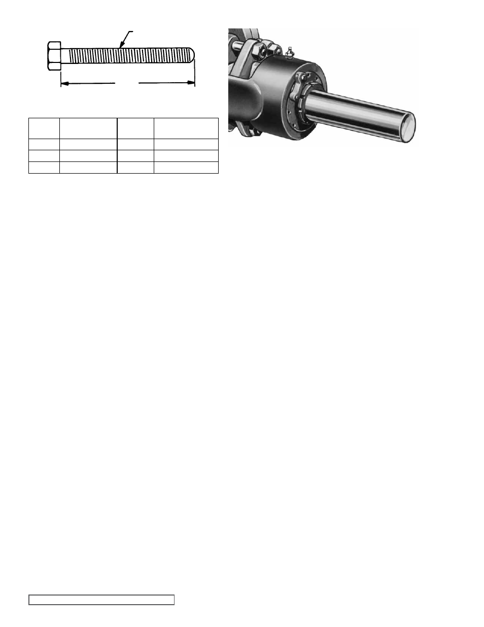
THREAD SIZE
a
MINIMUM LENgTH OF JACK SCREWS
FIgURE 6
FIgURE 7
LOCKWASHER WITH TANg
LOCKNUT
PUMP
SIZE
NO. SCREWS
USED
a
THREAD SIZE
(INCH)
N
2
4.00
0.50” - 13 NC
R
2
4.50
0.63” - 11 NC
P
3
5.00
0.50” - 13 NC
2. Remove head gasket, idler and bushing assembly.
3. Remove pipe plug from drain hole in casing, this breaks
vacuum behind rotor.
4. Remove packing gland nuts and slide gland out of rotor
bearing sleeve.
5. Insert length of hard wood or brass bar through port
opening between rotor teeth to keep shaft from turning.
6. Bend up tang on lock washer and with a spanner wrench;
remove locknut and lockwasher from shaft.
Refer to
figure 7.
7. Remove length of hardwood or brass bar from port
opening.
8. Cushion end of shaft with a hardwood block or piece of
block and drive rotor out of casing, being careful to avoid
damaging rotor bearing sleeve bushing. Support weight
of rotor with a hoist. A cable sling can be used around
shaft, or around rotor teeth, to carry weight of part.
9. Loosen end cap lockscrews, disengage end cap locks
and with a spanner wrench remove end caps. Remove
roller bearings.
10. Remove nuts and capscrews and take off thrust bearing
housing. Remove packing from rotor bearing sleeve.
11. Check rotor bearing sleeve bushing while rotor bearing
sleeve is mounted on casing. If worn, bushing must be
replaced.
Disconnect suck back line and remove rotor bearing
sleeve from casing. A press must be used to remove
old bushing. If bushing has a shoulder on the stuffing
box end, it must be pressed out packing end of rotor
bearing sleeve. If bushing is carbon graphite,
refer to
INSTALLATION OF CARBON gRAPHITE BUSHINgS,
page 14
12. Clean all parts thoroughly and examine for wear and
damage. Check idler bushing and idler pin, replace if
necessary.
If idler pin is to be replaced, oil must be installed facing
center of crescent head.
If lipseals need replacement, press in end cap with lip
facing end of shaft.
If idler bushing is to be replaced, a press must be used to
remove old bushing and install new. Bushing position after
being pressed in should be flush with face of idler. For
carbon graphite idler bushing,
refer to INSTALLATION
OF CARBON gRAPHITE BUSHINgS, page 14.
Wash anti-friction bearings (roller bearings) in clean
solvent. Blow out bearings with compressed air. Do
not allow bearings to spin; turn bearing slowly by
hand. Spinning bearings will damage race and rollers.
Make sure bearings are clean, then lubricate with non-
detergent SAE 30 weight oil and check for roughness.
Roughness can be determined by turning outer race
by hand.
CAUTION: do not intermix inner and outer
races for roller bearings. Replace bearings if they have
roughness.
Examine casing for wear. Check condition of casing
at seal area (surface between suction and discharge
port). If surface is in good condition, casing need not be
replaced.
When making major repairs, such as replacement of a
rotor, it is usually considered advisable to install a new
head and idler. When making minor repairs, where only
an idler bushing and idler pin are required, other new
parts are usually not necessary.