Disassembly, Danger – Viking Pump TSM153: N-R 333/4333 User Manual
Page 5
SECTION TSM 153
ISSUE
D
PAGE 5 OF 16
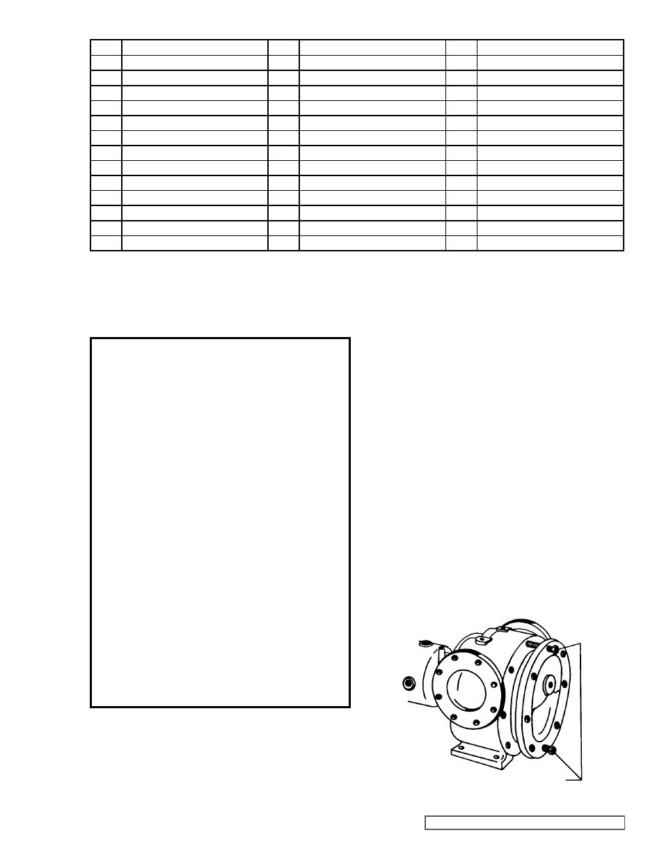
JACKSCREWS
DISASSEMBLY
DANgER !
Before opening any Viking pump liquid
chamber (pumping chamber, reservoir,
relief valve adjusting cap fitting, etc.)
Be sure:
1. That any pressure in the chamber has
been completely vented through the
suction or discharge lines or other
appropriate openings or connections.
2. That the driving means (motor,
turbine, engine, etc.) has been “locked
out” or made non-operational so that
it cannot be started while work is
being done on pump.
3. That you know what liquid the
pump has been handling and the
precautions necessary to safely
handle the liquid. Obtain a material
safety data sheet (MSDS) for the
liquid to be sure these precautions
are understood.
Failure to follow above listed
precautionary measures may result in
serious injury or death.
DETAILS FOR SECTIONAL VIEW - MODELS N AND R333
ITEM
NAME OF PART
ITEM
NAME OF PART
ITEM
NAME OF PART
1
Locknut
14
Bushing, Rotor Bearing Sleeve
27
Bearing Housing Stand
2
Lockwasher
15
Casing
28
Packing Gland Stud
3
Bearing Spacer Collar
16
Rotor and Shaft
29
Packing Gland Nut
4
Capscrew for End Cap Lock
17
Idler and Bushing
30
Bearing Housing Stud
5
End Cap Lock
18
Idler Bushing
31
Bearing Housing Nut
6
Lip Seal
19
Idler Pin
32
Bearing Housing Capscrew
7
End Cap
20
Head and Idler Pin
33
Stud for Rotor Bearing Sleeve
8
Roller Bearing
21
Nut for Head
34
Nut for Rotor Bearing Sleeve
9
Grease Fitting
22
Stud for Head
35
Rotor Bearing Sleeve Gasket
10
Thrust Bearing Housing
23
Capscrew for Valve
36
Pipe Plug
11
Packing Gland
24
Idler Pin Nut (Not N)
37
Head Gasket
12
Rotor Bearing Sleeve & Bushing
25
Internal Relief Valve
38
Relief Valve Gasket
13
Packing
26
Pipe Plug
*
Suckback Line (Not Illustrated)
1. Mark head and casing before disassembly to ensure
proper reassembly. The idler pin, which is offset in pump
head, must be positioned towards and equal distance
between port connections to allow for proper flow of
liquid through pump.
It is not necessary to remove relief valve to take head
off pump; however, removing relief valve will lessen total
weight of part. Do not use chain or cable around relief
value body to support the head during removal.
For
Pressure Relief Instructions, refer to page 14.
Remove nuts from head. Jackscrews should be used to
back head away from casing.
Refer to figure 5. Proper
size and length of jackscrews for pump size are shown in
figure 6. The use of a hoist to support head will facilitate
its removal.
Back head away from casing. Remove head from pump.
Do not allow idler to fall from idler pin. To prevent this,
tilt top of head back when removing. A lifting hook will
provide adequate connection for hoisting head. If a hoist
is not available, cribbing or blocking can be used to
support head. This will eliminate having to lift head into
position when reassembling pump.
FIgURE 5