Disassembly – Viking Pump TSM153: N-R 333/4333 User Manual
Page 15
SECTION TSM 153
ISSUE
D
PAGE 15 OF 16
DISASSEMBLY
DANgER !
Before opening any Viking pump liquid
chamber (pumping chamber, reservoir,
relief valve adjusting cap fitting, etc.)
Be sure:
1. That any pressure in the chamber has
been completely vented through the
suction or discharge lines or other
appropriate openings or connections.
2. That the driving means (motor,
turbine, engine, etc.) has been “locked
out” or made non-operational so that
it cannot be started while work is
being done on pump.
3. That you know what liquid the
pump has been handling and the
precautions necessary to safely
handle the liquid. Obtain a material
safety data sheet (MSDS) for the
liquid to be sure these precautions
are understood.
Failure to follow above listed
precautionary measures may result in
serious injury or death.
INSTALLATION OF CARBON
gRAPHITE BUSHINgS
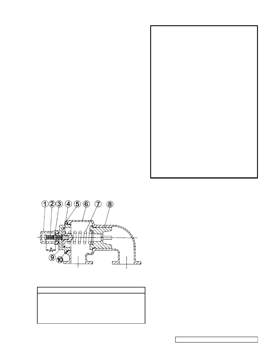
PRESSURE RELIEF VALVE
INSTRUCTIONS
FIgURE 19
N AND R SIZE
VALVE - LIST OF PARTS
1. Valve Cap
6. Valve Body
2. Adjusting Screw
7. Valve Spring
3. Lock Nut
8. Poppet
4. Spring Guide
9. Cap Gasket
5. Bonnet
10. Bonnet Gasket
When installing carbon graphite bushings, extreme care
must be taken to prevent breaking. Carbon graphite is a
brittle material and easily cracked. If cracked, the bushing will
quickly disintegrate. Using a lubricant and adding a chamfer
on the bushing and the matting part will help in installation.
The additional precautions listed below must be followed for
proper installation.
1. A press must be used for installation.
2. Be certain bushing is started straight.
3. Do not stop pressing operation until bushing is in proper
position, starting and stopping will result in a cracked
bushing.
4. Check bushing for cracks after installation.
Carbon graphite bushings with extra interference fits are
frequently furnished for high temperature operation. These
bushings must be installed by a shrink fit.
1. Heat rotor bearing sleeve or idler to 750º F.
2. Install cool bushings with a press.
3. If facilities are not available to reach 750º F. temperature,
it is possible to install with 450º F. temperature; however,
the lowering the temperature, the greater the possibility
of cracking bushing.
Consult factory with specific questions on high temperature
applications. Refer to Engineering Service Bulletin ESB-3.
Mark valve and head before disassembly to ensure proper
reassembly.
1. Remove valve cap.
2. Measure a record length of extension of adjusting
screw.
Refer to “A” on Figure 19.
3. Loosen locknut and back out adjusting screw until spring
pressure is being released.
4. Remove bonnet, spring guide, spring and poppet from
valve body. Clean and inspect all parts for wear and
damage and replace as necessary.