Optional mechanical seal (ptfe fitted type), Danger – Viking Pump TSM153: N-R 333/4333 User Manual
Page 13
SECTION TSM 153
ISSUE
D
PAGE 13 OF 16
DANgER !
Before starting pump, be sure all drive
equipment guards are in place.
Failure to properly mount guards may
result in serious injury or death.
FIgURE 17
11. Slide seal spring on shaft and into seal chamber against
set collar. Place spring adapter, open side facing end of
shaft against spring. Place tapered installation sleeve on
shaft.
NOTE: Tapered installation sleeve available from factory,
at additional cost, for N & R size pumps.
12. Apply generous amount of non-detergent SAE 30 weight
oil to large diameter of shaft, tapered installation sleeve
and inner diameter of mechanical seal rubber parts.
13. Coat seal holder chamber and O-ring seat gasket with
non-detergent SAE 30 weight oil and press in seal seat
with lapped faced out. Protect face of seal seat with a
clean piece of cardboard while pressing into place.
14. Coat seal holder plate O-ring gasket with non-detergent
SAE 30 weight oil and install over pilot of plate.
15. Coat inside diameter of rotating face of seal with non-
detergent SAE 30 weight oil and start tail of bellows
over installation sleeve on shaft. A twisting motion while
pushing will aid in sliding seal on sleeve. Push seal
against seal adapter. Do not touch carbon rotating face
with anything except clean hands or clean cloth.
Check to make sure adapter is not cocked.
16. Install seal holder plate over shaft on mounting studs
until seal faces touch.
Start nuts on mounting studs. Pull seal holder plate
evenly against face of seal chamber with nuts,
alternately tightening one and then the other. This will
compress mechanical seal to correct operating length
and compress plate gasket to seal off seal chamber.
17. Remove tapered installation sleeve.
18. Place inner end cap with lipseal (lip facing end of shaft)
on shaft.
19. Install thrust bearing housing on end of rotor bearing
sleeve and tighten nuts and capscrews securely.
It is not necessary to use gasket between these parts.
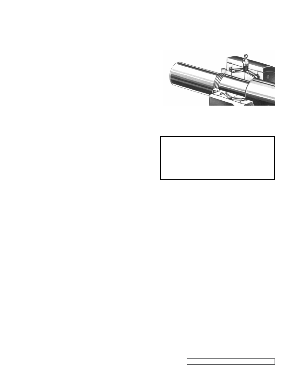
20. Insert both tapered roller bearings in thrust bearing
housing, large end of inner races together.
CAUTION: It is possible to install bearings incorrectly.
For proper assembly,
refer to Figure 17.
21. Install bearing spacer collar on shaft next to inner race of
roller bearing.
22. Turn inner end cap into thrust bearing housing just far
enough to hold in place.
Install outer end cap and turn in approximately half way.
23. Insert length of hardwood or brass bar through port
opening between rotor teeth, to keep rotor from turning.
24. Install lockwasher with tang in keyway on shaft. Tighten
locknut to 170-190 ft.-lbs. Torque. Bend one tang of
lockwasher into slot of locknut. If tang does not line up
with slot, tighten locknut until it does. Failure to tighten
locknut or engage lockwasher tang could result in early
bearing failure and cause damage to rest of pump. Bend
one tang of lock washer into slot of locknut.
25. Remove length of hardwood or brass bar from port
opening.
26. Reinstall flush tubing from casing discharge port gage
hole to rotor bearing sleeve.
27. Lubricate all grease fittings with multi-purpose grease,
NLGI # 2.
28. Adjust pump end clearance. Refer to THRUST BEARINg
ADJUSTMENT, page 14.
OPTIONAL MECHANICAL SEAL
(PTFE Fitted Type)
Three components are furnished in mechanical seal
assembly:
Refer to figure 18, item numbers 1 thru 6.
1. Rotating assembly in which a retainer cartridge encloses
a spring loaded PTFE shaft ring and polished rotating
face. Set screws located around the outside of retainer
cartridge are provided for securing rotating assembly to
pump shaft.
2. Stationary seal seat.
3. Two seal seat gaskets.
Three pump parts necessary for mounting PTFE
mechanical seal are illustrated in
figure 18, item letters
A, B, C and D.
1. Packing box extension. Has machine pilot on end for
installation in rotor bearing sleeve and two tapped holes
for seal flush.
2. Packing box extension gasket.
3. Seal plate. Machined to accept seal seat and gasket.