Disassembly assembly, Thrust bearing adjustment – Viking Pump TSM153: N-R 333/4333 User Manual
Page 14
SECTION TSM 153
ISSUE
D
PAGE 14 OF 16
SHAFT
DISASSEMBLY
ASSEMBLY
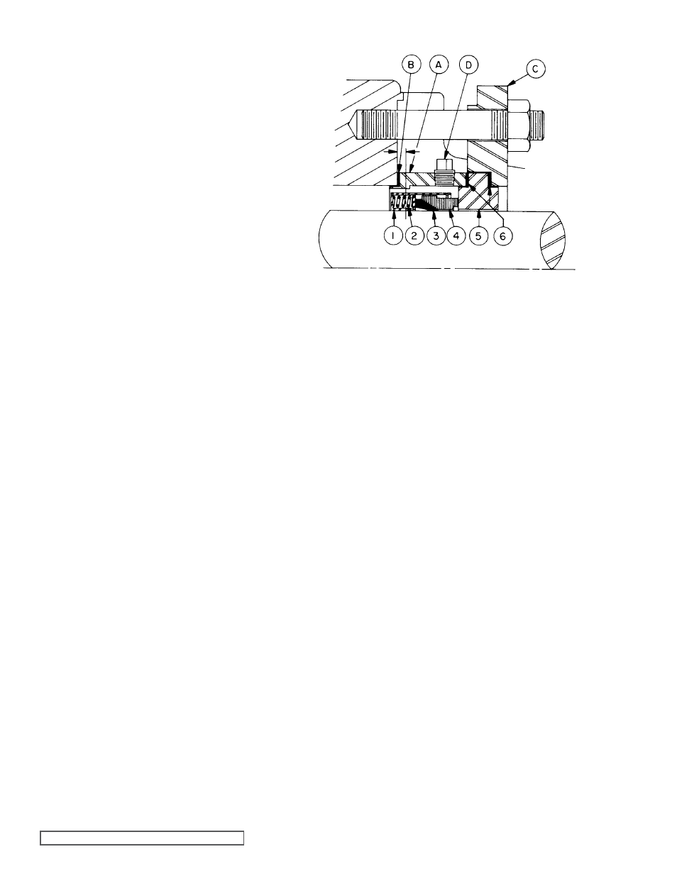
FIgURE 18
1. Disassemble pump per steps 1 thru 10 on page 9, under
MECHANICAL SEAL DISASSEMBLY.
2. Remove seal plate nuts from studs and remove seal
plate, gaskets and stationary seat.
3. If pump is equipped with a flush line, disconnect from
packing box extension.
4. Remove packing box extension and gasket.
5. Loosen set screws in mechanical seal retainer cartridge
and remove from rotor shaft. Refer to figure 18.
1. Reassemble pump per steps 1 thru 9 on pages 11 & 12,
under
Assembly, Standard Mechanical Seal. Step 1
(deburring shaft) is very critical prior to seal assembly.
2. A tapered seal installation sleeve for N & R size pumps
is available, at no extra cost, from Viking Pump.
3. Coat large diameter of shaft, tapered sleeve, and inside
diameter of seal with non-detergent SAE 30 weight oil.
4. Place tapered installation sleeve (if on hand) and install
seal on shaft over tapered sleeve. Position seal on shaft
inside rotor bearing sleeve bore with end of seal located.
19 inch inside machined face of rotor bearing sleeve.
Refer to Figure 18.
5. Tighten all seal drive set screws securely to shaft.
6. Remove tapered installation sleeve.
7. Place gasket on packing box extension and install
extension with machined pilot inside rotor bearing sleeve
bore.
8. Place seat gasket over shoulder of stationary seal seat
and insert set into seal plate. Place remaining seat
gasket over shoulder of polished surface of stationary
seat.
Refer to Figure 18.
9. Place seal plate with stationary seat over mounting studs
and push shoulder of stationary seat into packing box
extension, polished face against carbon rotating face.
10. Install nuts on mounting studs and against seal holder.
Tighten nuts evenly so seal plate and stationary seat will
not be distorted when seal is compressed.
11. Reassemble flush line to packing box extension.
AT THIS POINT, FINISH ASSEMBLY PROCEDURES
STARTINg AT STEP 18, page 12.
PTFE Fitted Mechanical Seal Assembly
For Models N-R4333, 4335 & 4337
1. Retainer Cartridge
2. Springs
3. PTFE Shaft Ring (wedge)
4. Rotating Face (washer)
5. Stationary Seal Seat
6. Seat Gaskets
Seal Mounting Parts
A. Packing box extension
B. Packing box extension gasket
C. Seal plate
D. Flush openings
THRUST BEARINg ADJUSTMENT
Use spanner wrench (provided with pump) and turn outer
end cap until rotor is tight against head and rotor shaft cannot
be turned.
With pencil or chalk, make reference mark on bearing housing
and outer end cap. Back off outer end cap approximately
4 holes. One hole is equivalent to .005” end of clearance.
Tighten inner end cap. Check rotor to determine if it turns
freely in the casing. If not, make further adjustment until rotor
does turn in casing.
Standard catalogue pumps require the following end
clearance settings; N, 015”, R, .020” minimum. Pumps built
for viscous liquid or high temperatures service may require
extra end clearance. Consult factory.
Lock both end caps securely in position with end cap locks
and screws.