Transmig 250i installation/setup – Tweco 250i Multi Process Welding Inverter 2RT Wire Feeder User Manual
Page 54
TRANSMIG 250i
INSTALLATION/SETUP
INSTALLATION/SETUP 3-36
Manual 0-5187
6. The tungsten must be ground to a blunt point (similar to a pencil) in order to achieve optimum welding results.
See illustration. It is critical to grind the tungsten electrode in the direction the grinding wheel is turning. Grind
at a 30 degree angle and never to a sharp point.
A-00503_AB
Electrode
2 to 2-1/2 Times
Electrode Diameter
Figure 3-31: Electrode sharpening
7. Install the tungsten with approximately 3.2mm to 6.4mm sticking out from the gas cup, ensuring you have
correct sized collet.
8. Tighten the back cap.
9. Turn the switch to the “ON” position. The power L.E.D. light should illuminate.
10. Set the welding process to LIFT TIG.
11. Set the Weld Current Control Knob to the desired amperage.
+
-
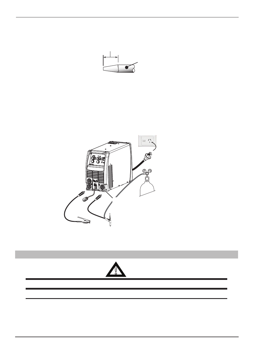
Art # A-10284
Negative Output
Terminal
(Dinse® type 50mm)
Ensure that the gas
cylinder is secured to
a building pillar, wall
bracket or otherwise
securely fixed in an
upright position.
Figure 3-32: Setup for LIFT TIG (GTAW) Welding
12. You are now ready to begin LIFT TIG Welding.
3.26 Set-up for Metal Manual Metal Arc Welding (MMAW)
!
WARNING
Before any welding is to begin, be sure to wear all appropriate and recommended safety equipment.
NOTE
The following set up is known as DC Electrode Positive or reverse polarity. Please consult with the stick
electrode manufacturer for specific polarity recommendations.
1. Switch the ON/OFF Switch (located on the rear panel) to OFF.
2. Attach the stick and work leads as shown in Figure 3-33.