07 advanced features details, Advanced features details -10, Transmig 250i installation/setup – Tweco 250i Multi Process Welding Inverter 2RT Wire Feeder User Manual
Page 28
TRANSMIG 250i
INSTALLATION/SETUP
INSTALLATION/SETUP
3-10
Manual 0-5187
15. Negative Welding Output Terminal
The negative welding terminal is used to connect the
welding output of the power source to the appropriate
welding accessory such as the MIG Torch (via the MIG
Torch polarity lead), TIG torch or work lead. Negative
welding current fl ows to the power source via this
heavy duty bayonet type terminal. It is essential,
however, that the male plug is inserted and turned
securely to achieve a sound electrical connection.
CAUTION
Loose welding terminal connections can cause
overheating and result in the male plug being
fused in the bayonet terminal.
16. MIG Torch Polarity Lead
The polarity lead is used to connect the MIG Torch to
the appropriate positive or negative output terminal
(allowing polarity reversal for different welding ap-
plications). In general, the polarity lead should be
connected in to the positive welding terminal (+) when
using steel, stainless steel or aluminium electrode
wire. When using gasless wire, the polarity lead is
generally connected to the negative welding termi-
nal (-). If in doubt, consult the manufacturer of the
electrode wire for the correct polarity. It is essential,
however, that the male plug is inserted and turned
securely to achieve a sound electrical connection.
CAUTION
Loose welding terminal connections can cause
overheating and result in the male plug being
fused in the bayonet terminal.
3.07 Advanced Features Details
NOTE
The "LOCL/ REMT" settings will revert to the
factory default setting each time the weld
process is changed. A setting other than the
default will only be remembered while in that
process.
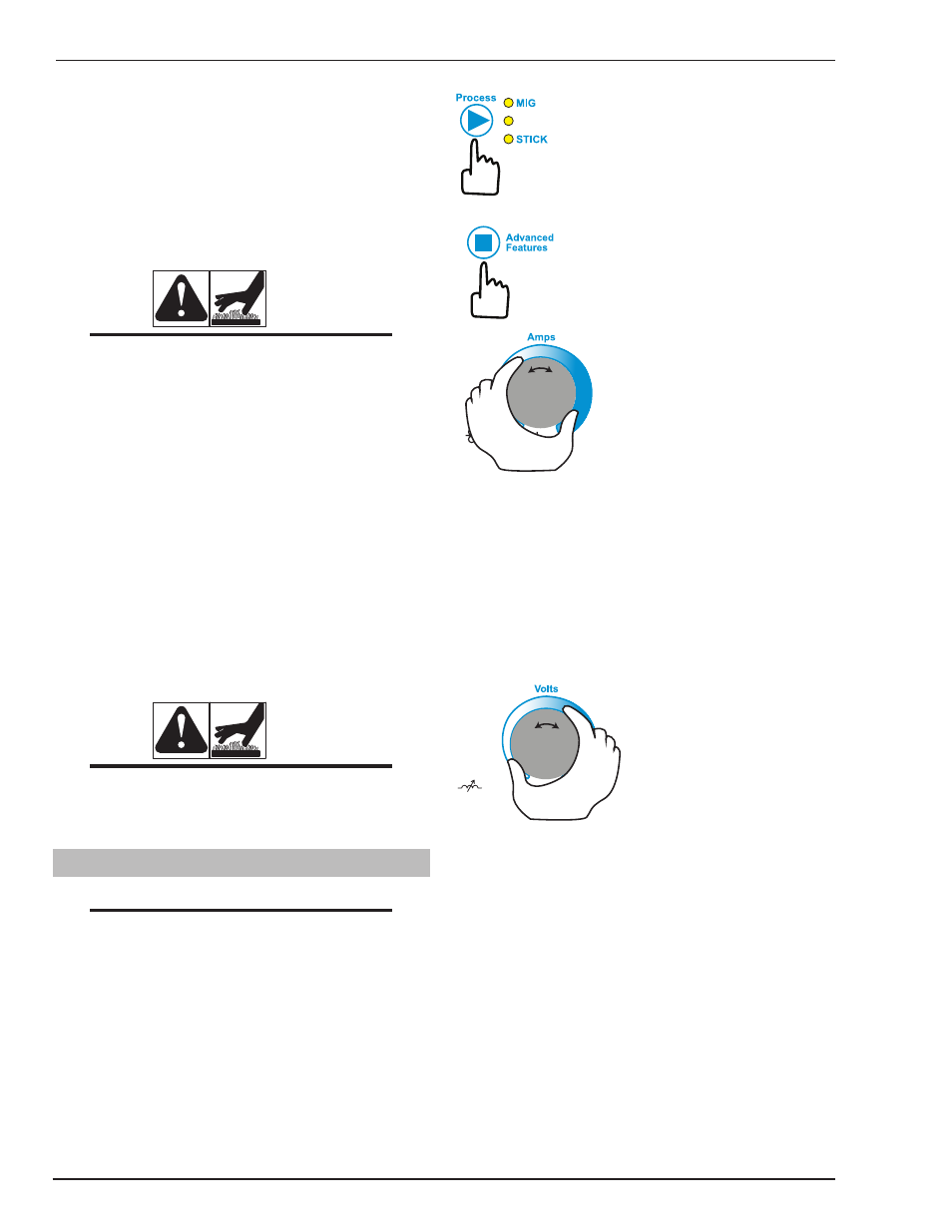
General Operation
LIFT TIG
Select the weld process (Control No 4)
you wish to view Advanced Features
for.
Then press and release the Advanced Fea-
tures button (Control No 6) to enter or exit
from the Advanced Features programming
function of the welder.
Left Knob
The Advanced Features menu items are viewed by turning
the left knob (Control No 7) to move forward or backward
through the list. The function names in the menu will be
displayed in abbreviated form in the left alpha-numeric
display. In the case of two part names or abbreviations,
the left display will alternately fl ash the fi rst part of the
function name and then the second part, followed by a
brief “blank” interval. For each function, the right alpha-
numeric display will show its present value.
Push For Inductance
Arc Control
Right Knob
To change the value of that parameter, simply turn the
right knob (Control No 8) to change it. If the setting has
been changed from its previous value the welder will save
the new value when the left knob is turned to view the
next parameter, or if the user activates a control to cause
the welder to exit Advanced Features mode as described
earlier. Once the beginning or end of the menu list is
reached, additional turning of the left knob in that direction
will not result in any change of the displayed parameter.
The Advanced Features control functions are in order with
the user’s process steps when setting up to operate the
welder in the selected welding process modes (MIG, LIFT
TIG, STICK). The menu functions shown in Advanced
Features Mode are mostly dependent on the currently
selected weld process mode of the machine.