Transmig 250i installation/setup – Tweco 250i Multi Process Welding Inverter 2RT Wire Feeder User Manual
Page 34
TRANSMIG 250i
INSTALLATION/SETUP
INSTALLATION/SETUP 3-16
Manual 0-5187
Volts
Wirespeed
Left Knob
Right Knob
WFS Control
Volts Control
Euro Connector
8 Pin Remote
Connector
Art # A-10324
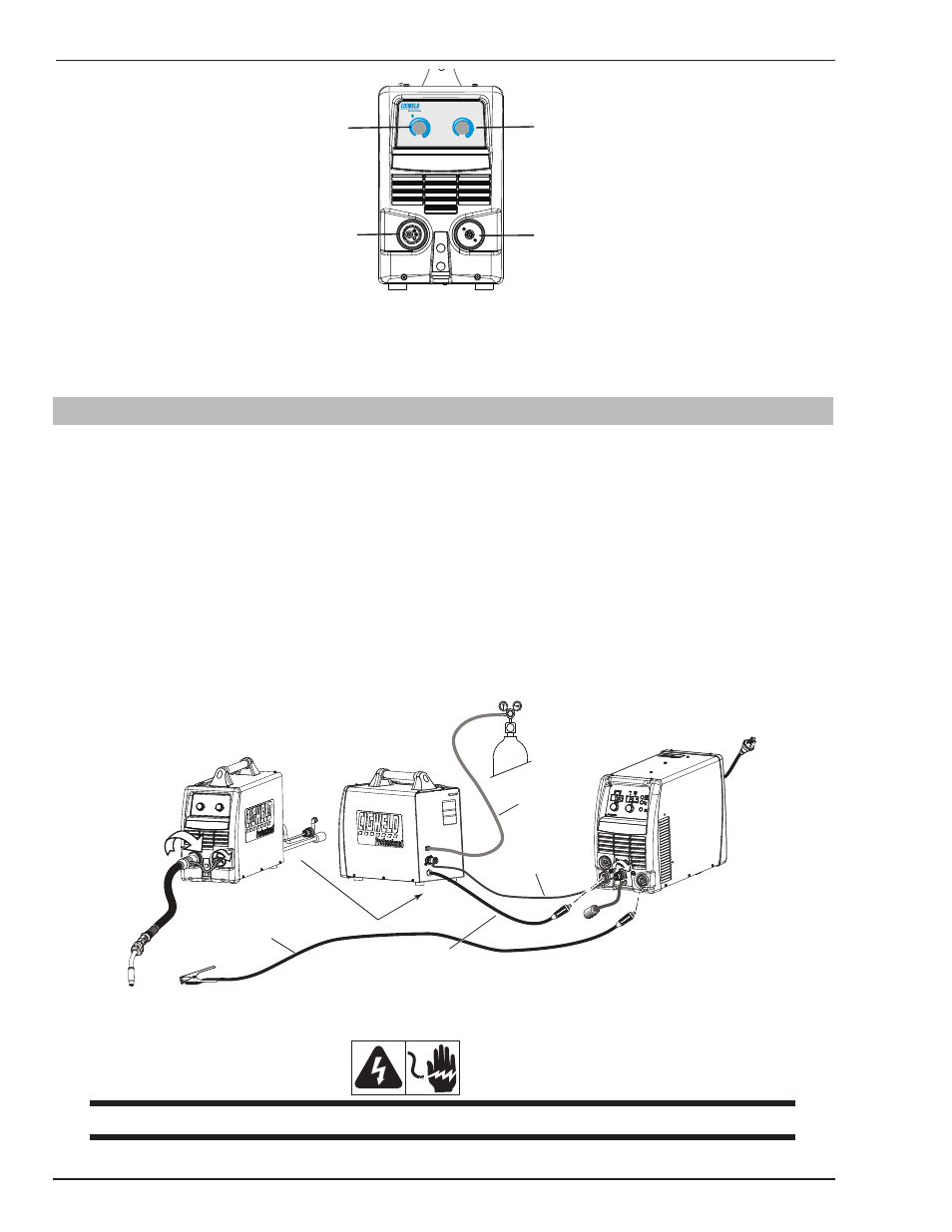
Figure 3-8: 2RT Front Panel Controls
The Tweco professional MIG Torch will connect to the 2RT just as it does to the 250i power source. The electrode
Polarity setting is done at the power source. See section 3.23 and 3-24.
3.09 Optional Wire Feeder Set Up MIG (GMAW) Welding with Gas Shielded MIG Wire
The Transmig 250i is supplied with a Tweco Fusion 250 AMP air-cooled MIG Torch. The Fusion MIG Torch is designed
with an ergonomic handle and fewer parts to reduce performance problems. The Fusion MIG Torch uses standard
readily available Tweco consumable parts.
When using a Gas Shielded wire with the 2RT Wire Feeder, you need to have an external gas source attached to the 2RT.
For most Gas Shielded wire, connect the Work Lead to the negative - terminal on the front of the 250i and connect
the Welding Power Cable from the back of the 2RT to the positive + terminal on the front of the 250i. Check with wire
manufacturer for recommended polarity.
The 2RT Wire Feeder is fitted with an 8M interconnection cable assembly to connect from the back of the 2RT to the
front of the 250i welding power source.
Connect the MIG Torch to the front of the 2RT as you would to the front of the 250i in Sections 3.23 and 3.24.
+
-
Front View 2RT
Rear View 2RT
Front View 250i
Control Cable
Welding Power Cable
from Wire Feeder
Work Lead
Art # 10335
Gas Hose
Figure 3-9: Setup for 2RT Wirefeeder
WARNING
Before connecting the work clamp to the work make sure the mains power supply is switched OFF.