Transmig 200i – Tweco 200i Multi Process Welding Inverter User Manual
Page 25
TRANSMIG 200i
Manual 0-5209
3-7
INSTALLATION, OPERATION AND SETUP
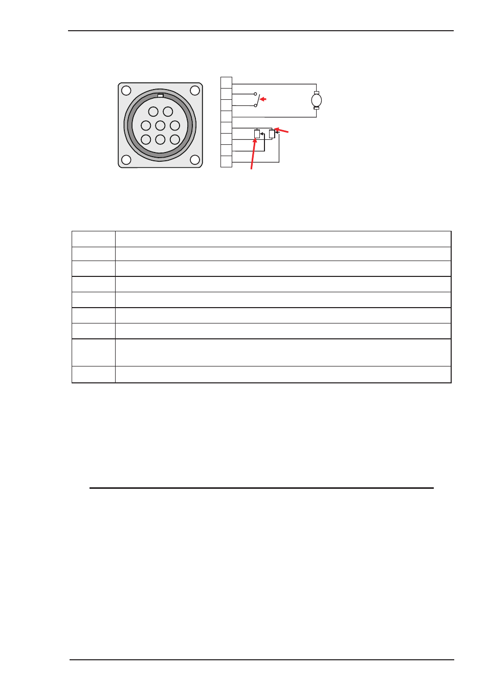
9. Remote Control Socket
The 8 pin Remote Control Socket is used to connect remote control devices to the welding power source.
To make connections, align keyway, insert plug, and rotate threaded collar fully clockwise.
Trigger Switch
Remote Wirespeed in GMAW mode
Remote Amps in GTAW mode
Remote Volts in
GMAW Mode
1
2
3
4
5
6
7
8
W V
3
4
5
6
7
8
1
2
Negative
Spool Gun Motor
Positive
Art # A-10421
Figure 3-3: Remote Control Socket
Socket Pin
Function
1
Spool Gun Motor Negative
2
Trigger Switch Input
3
Trigger Switch Input
4
Spool Gun Motor Positive
5
5k ohm (maximum) connection to 5k ohm remote control potentiometer.
6
Zero ohm (minimum) connection to 5k ohm remote control potentiometer.
7
Wiper arm connection to 5k ohm remote control Wirespeed GMAW (MIG) mode potentiometer.
Wiper arm connection to 5k ohm remote control Amps GTAW (TIG) mode potentiometer.
8
Wiper arm connection to 5k ohm remote control Volts GMAW (MIG) mode potentiometer.
Table 3-1
Note that the remote local switch (item 18) located in the wirefeed compartment should be set to remote
for the amperage/voltage controls to be operative.
10. Multifunction Control - Voltage, Down Slope & Arc Force
The multifunction control knob is used to adjust Voltage (MIG Mode), Down slope (TIG Mode) and Arc
Force (STICK Mode) depending on the welding mode selected.
NOTE
The preview functionality provided on this power source is intended to act as a guide only. Some
differences may be observed between preview values and actual welding values due to factors
including the mode of welding, differences in consumables/gas mixtures, individual welding
techniques and the transfer mode of the welding arc (ie dip versus spray transfer). Where exact
settings are required (in the case of procedural work), it is recommended that alternate measurement
methods be utilised to ensure output values are accurate.
When GMAW/FCAW (MIG) Mode is Selected
In this mode the control knob is used to adjust the output voltage of the unit. The welding voltage is
increased by turning the knob clockwise or decreased by turning the knob anti-clockwise. The optimum
voltage level required will dependent on the type of welding application. The setup chart on the inside
of the wire feed compartment door provides a brief summary of the required output settings for a basic
range of MIG welding applications.