06 prewelding procedure, 07 welding - 2 step operation, Ultrafeed va 4000 – Tweco VA 4000 Ultra-Feed User Manual
Page 34
ULTRAFEED VA 4000
4-6
September 18, 2012
WARNING
In semiautomatic or automatic wire welding,
the welding wire, wire reel (if used), input
guide, feed rolls, output guide, feedhead, and
welding gun metal parts are all ELECTRICALLY
“HOT”.
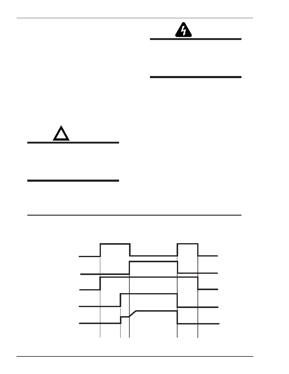
4.07 Welding - 2 Step Operation
Refer to Figure 4-5.
Position the welding gun above the workpiece and de-
press the gun switch trigger. Depressing the gun switch
trigger enables the gas valve, wire feed motor, and power
source; the welding process begins. To end the weld, re-
lease the gun switch trigger which disables the gas valve,
wire feed motor, and power source.
4.06 Prewelding Procedure
Follow all installation instructions for the wire feeder,
the welding power source, and the welding gun before
attempting to operate the Ultrafeed VA 4000.
1. Make sure all necessary connections have been
made (Refer to “Connections” in the Installation
chapter of this manual).
2. Turn ON the power source and the wire feeder.
3. Push the PURGE switch of the feeder and adjust
the flow of shielding gas.
4. Push the INCH switch of the feeder and adjust
the wire feed speed to the desired value by means
of the wire feed speed control.
!
WARNING
If the gun switch is depressed, the electrode
(welding wire) is electrically “hot”. Do not
permit it to touch any metal or a welding arc
may be established which may be injurious to
someone’s eyes (flash) or skin (burn).
5. Adjust the voltage of the power source to the
desired value. The gun switch must be triggered
to close power source contactor.
NOTE
When the gun switch is released, gas will continue to flow for approximately 0.5 seconds. This is a
feature of the system and is normal.
Gun Trigger
Arc Established
Gas
Contactor
WireFeed
Runin %
Postflow
Preflow
Ramp Rate
Art # A-06986