Ultrafeed va 4000 – Tweco VA 4000 Ultra-Feed User Manual
Page 31
ULTRAFEED VA 4000
September 18, 2012
4-3
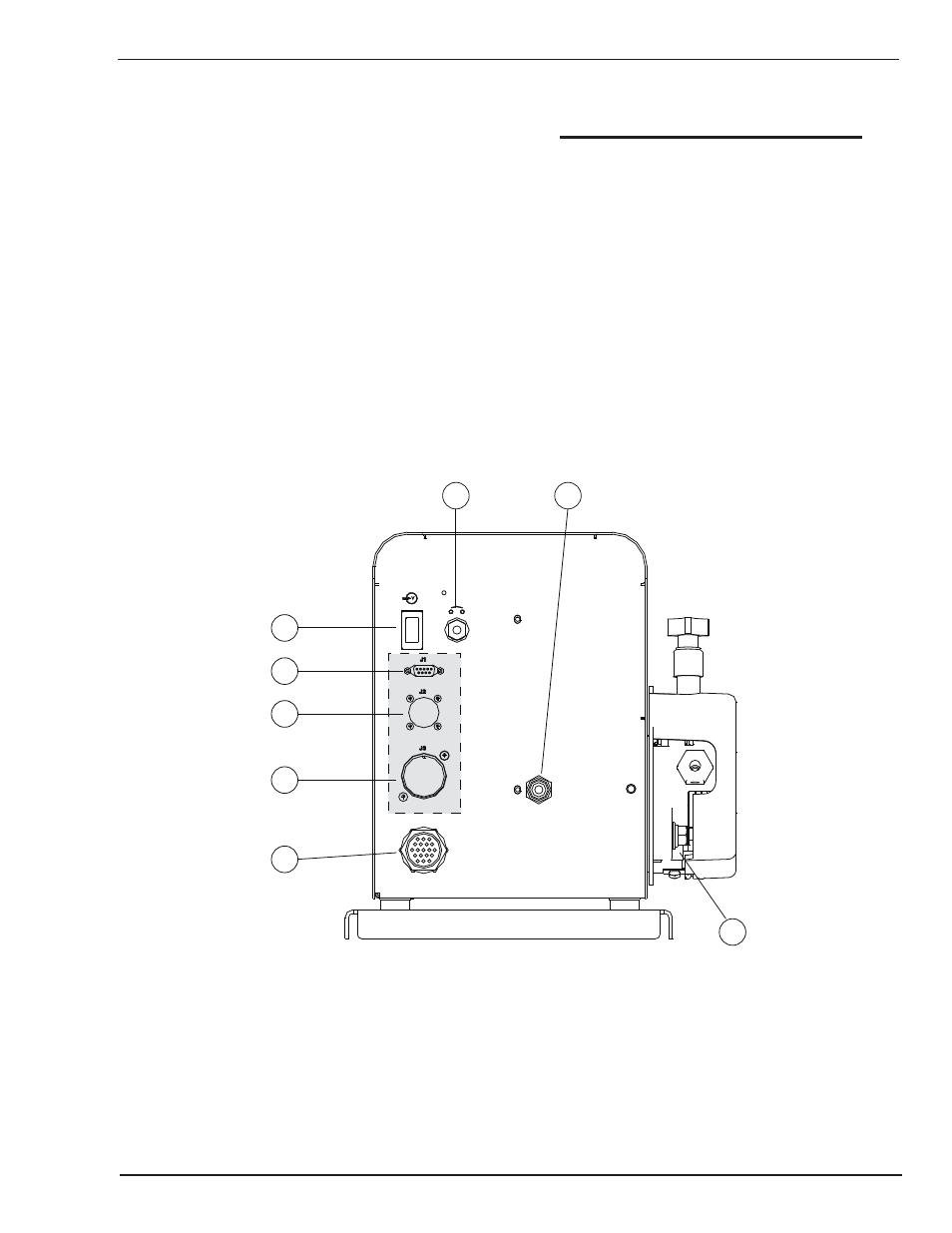
12.
AUXILIARY INTERFACE PORT (J3): These
connections are used by the advanced interface
kit.
13.
CAN INTERFACE PORT (J2): This connection
allows the ULTRAFEED VA 4000 to communicate
with other select Thermal Arc power sources. This
is available with the advanced interface kit.
14.
SERIAL PORT (J1): This connection allows the
ULTRAFEED VA 4000 to communicate with a
personal computer. This feature is available with
the advanced interface kit.
15.
POWER ON/OFF SWITCH: This switch controls
only the wire feeder and not the power source.
16.
CIRCUIT BREAKER: This breaker protects the
unit from electrical faults.
NOTE
If the circuit breaker trips, it turns the power
switch to the OFF position. A short cooling
period must be allowed before an attempt is
made to reset the unit by pressing the circuit
breaker reset switch.
17.GAS VALVE INLET: This is where the shielding gas
hose is connected to the wire feeder. The gas valve
inlet controls the “on/off” flow of shielding gas through
the welding gun.
18.WELD CABLE CONNECTION: This is where the power
source welding cable is connected to the feeder. Make
sure this connection is tight or arcing could occur.
11
12
13
14
15
16
17
18
Art # A-06985
Figure 4-3: Rear Panel Controls and Connections