04 electrical input requirements – Tweco 300 ACDC Arcmaster User Manual
Page 21
15
3.04 Electrical Input Requirements
Operate the welding power source from a single-phase 50/60 Hz, AC power supply. The input voltage
must match one of the electrical input voltages shown on the input data label on the unit nameplate.
Contact the local electric utility for information about the type of electrical service available, how proper
connections should be made, and any inspection required.
The line disconnect switch provides a safe and convenient means to completely remove all electrical
power from the welding power supply whenever necessary to inspect or service the unit.
Note
This unit is equipped with a three-conductor with earth power cable that is connected at the welding
power source end for single and three phase electrical input power.
Do not connect an input (BROWN or BLUE or RED) conductor to the ground terminal.
Do not connect the ground (YELLOW/GREEN) conductor to an input line terminal.
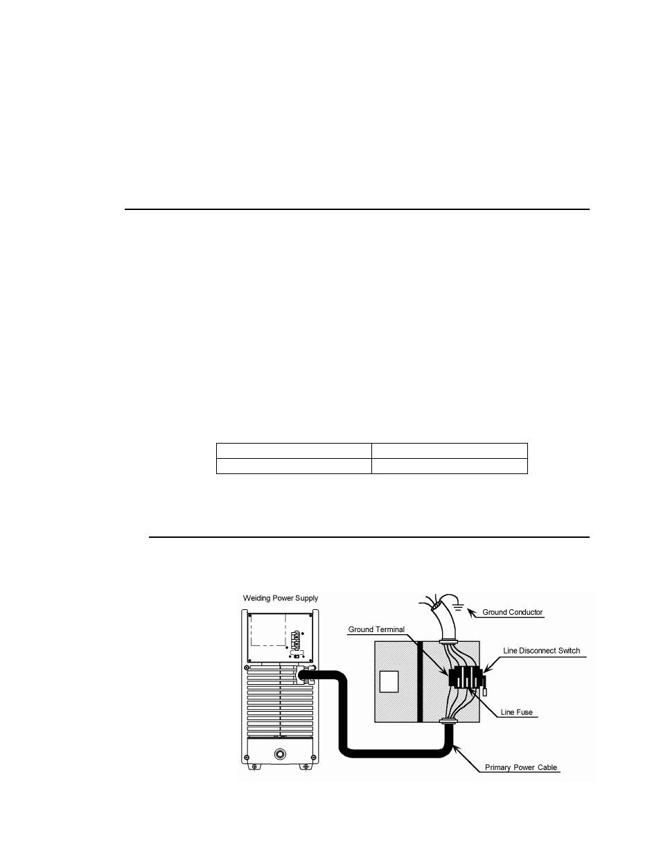
Refer to Figure 3:
1. Connect end of ground (YELLOW/GREEN) conductor to a suitable ground. Use a grounding method that
complies with all applicable electrical codes.
2. Connect ends of line 1 (BROWN) and line 2 (BLUE) and line 3 (RED) input conductors to a
de-energized line disconnect switch.
3. Use Table 3-1 and Table 3-2 as a guide to select line fuses for the disconnect switch.
Input Voltage
Fuse Size
400V 60
Amps
Table 3-1. Electrical Input Connections
Note
Fuse size is based on not more than 200 percent of the rated input amperage of the welding
power source (Based on Article 630, National Electrical Code).
Figure 3-1. Electrical Input Connections