06 functional block diagrams, 07 transporting methods, Arcmaster 200 ac/dc – Tweco 200 ACDC Arcmaster(April2006) User Manual
Page 20
ARCMASTER 200 AC/DC
2-4
April 13, 2006
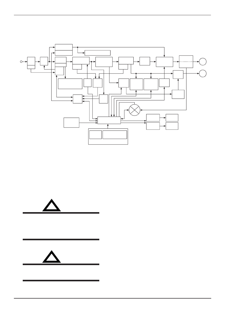
2.06 Functional Block Diagrams
Figure 2-2 illustrates the functional block diagram of the 200 AC/DC-power supply.
Main
Circuit
Switch
Filter
Input
Diode
Primary
Capacitor
DC Power
Voltage
Sensor
IGBT
Inverter
Thermal
Detector
To each control circuit
+/-15VDC +18VDC
+24VDC +5VDC
Trouble
Sensing
Circuit
Drive
Circuit
Torch Control
Connection
(CON1)
circuit
Current
Adjustment
Reference
Adjustment &
Mode select Switches
Panel Circuit Board
Sequence
Control
Themal
Sensor
Circuit
Main
Transformer
(PCB14)
Output
Diodes
HF-UNIT
Control
Circuit
Stick Mode
VRD
Sensing
Circuit
Lift T ig Mode
Output Short
Sensing
Circuit
Coupling
High
Coil
Frequency
Unit
Fan Control
Circuit
Gas Control
Circuit
Fan
Solenoid
Hall Current
Transformer
(HCT1)
Output
Inductor
Thermal
Detector
+
-
+
-
Input
Power
Secondary
DC Power
Voltage Sensor
To each control circuit
+/-12VDC +15VDC
Secondary
IGBT
Inverter
Drive
Circuit
Primary
Current
Sensor
Art # A-07267
Figure 2-2: 200 AC/DC Model Functional Block Diagram
2.07 Transporting Methods
This unit is equipped with a handle for carrying purposes.
!
WARNING
ELECTRIC SHOCK can kill. DO NOT TOUCH
live electrical parts. Disconnect input power
conductors from de-energized supply line
before moving the welding power source.
!
WARNING
FALLING EQUIPMENT can cause serious
personal injury and equipment damage.
• Lift unit with handle on top of case.
• Use handcart or similar device of adequate capacity.
• If using a fork lift vehicle, place and secure unit on a
proper skid before transporting.