Ultra-cut 100, Gcm 2010 – Tweco 100 Ultra-Cut User Manual
Page 72
OPERATION
4-6
Manual No. 0-4748
ULTRA-CUT 100
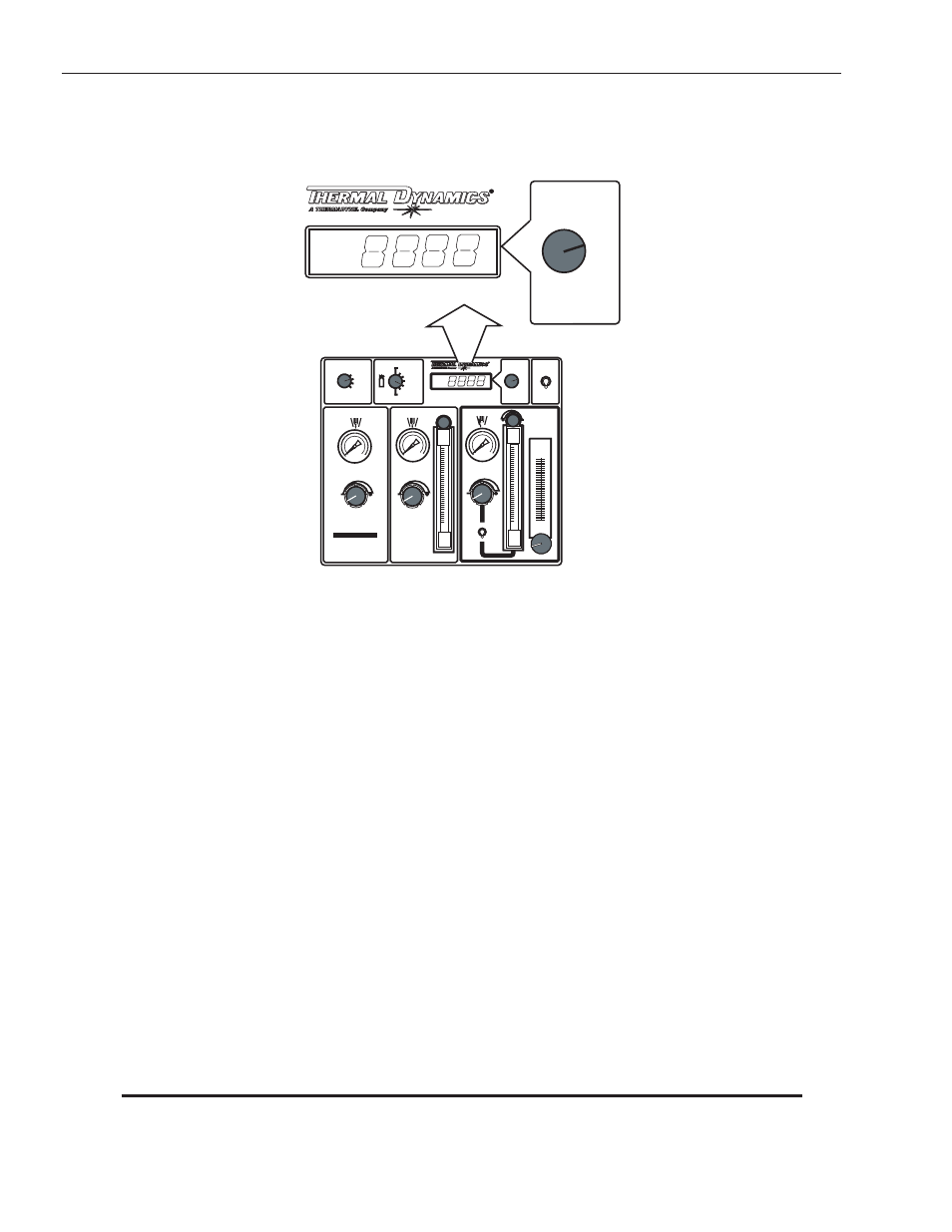
4. Current Control
Adjusts the output current of the power supply.
High Precision
Plasma Cutting System
PREFLOW
H
2
O
MIST
PLASMA
SHIELD
PRESSURE
PLASMA
POWER SUPPLY
GAS
FLOW
High Precision
Plasma Cutting System
ENABLE
DISABLE
GAS
MODE
RUN
SET PREFLOW
SET PLASMA
& SHIELD
TEST
O2 - AIR
O2 - O2
H35 -N
2
F5 - N
2
AIR - AIR
N
2 -
H
2
O
N
2 -
N
2
9
9
Art # A-04767
GCM
2010
5. Plasma Power Supply Enable / Disable Switch
The DISABLE position removes input power from the Power Supply inverters, disables the coolant pump and
fan, the pilot contactor & HF and removes AC power from the gsa control solenoids shutting off all gas flow.
When the switch is returned to the ENABLE position an automatic gas purge is started and then the system is
returned to normal operation under control of the CNC device.
6. PREFLOW Control Knob and Pressure Gauge
Used to set preflow gas pressure and flow. MODE switch must be in SET PREFLOW position.
7. PLASMA and SHIELD Control Knobs, Pressure Gauges and Flow Meter
Used to set plasma and shield gas pressures and flows. Mode switch must be in SET PLASMA & SHIELD
position.
8. Gas Pressure Flow Switch
At lower flow rates shield gas pressure is first set per the cut charts then the flow is set using the flow meter
with the GAS switch set in the FLOW position. Some torch parts require higher flow rates that execeed the
capacity of the flow meter. In that case, Gas switch is set in the PRESSURE position and the regulator and
gauge is used to set pressure per the cut charts when no “Ball” setting is shown.
9. H
2
O Mist Control Knob and Flow Meter
Used to set water flow rate. MODE switch must be in SET PLASMA & SHIELD position. GAS selection switch
must be in N
2
-H
2
O position.
NOTE
Water mist is not used in all applications.