Ultra-cut 100 – Tweco 100 Ultra-Cut User Manual
Page 123
Manual 0-4748
A-3
APPENDIX
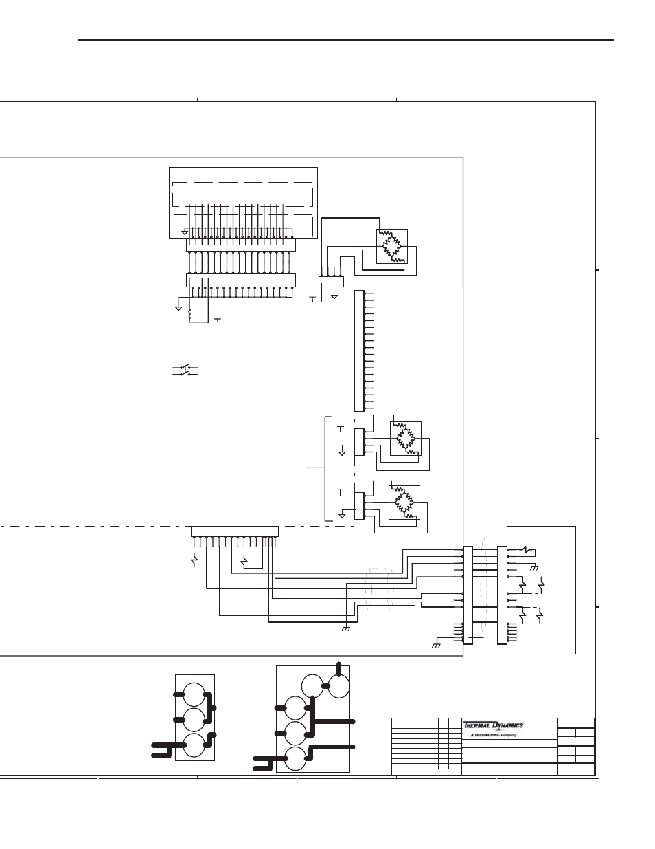
ULTRA-CUT 100
Art # A-07200
3
2
2
1
1
D
C
B
A
(46)
(47)
(43)
(45)
(45)
(42)
(42)
(44)
(44)
(40)
(49)
(48)
(40)
(40)
(40)
(40)
(40)
(40)
(41)
+5VDC
+5VDC
+5VDC
+5VDC
DWG No:
Sheet
of
Supersedes
Scale
Date:
Drawn:
References
Date
By
Revisions
Rev
PCB No:
Assy No:
Information Proprietary to THERMAL DYNAMICS CORPORATION.
Not For Release, Reproduction, or Distribution without Written Consent.
NOTE: UNLESS OTHERWISE SPECIFIED -
1. RESISTOR VALUES ARE EXPRESSED IN OHMS, 1/4W 5%.
2. CAPACITOR VALUES ARE EXPRESSED IN MICROFARADS (uF).
Chk:
App:
TITLE:
Last Modified:
Size
SCHEMATIC,
42X1202
Monday, January 29, 2007
1
1
Ultracut GCM 2010 Gas Control & TVA
Wednesday, January 26, 2005
13:57:13
D
LCD DISPLAY CONNECTOR
CURRENT CONTROL
(Thumbwheel)
optional
LCD DISPLAY
ULTRACUT TORCH VALVE
ASSEMBLY (TVA or TVA-XTL)
DAT
RIBBON
CABLE
15 16
1
2
{
INTERFACE
BOARD
3
4
5
6
7
8
9
10 11 12 13 14
FERRITE
CORE
Safety Gnd
(low freq)
RF Gnd
(Shield)
AA
ECO-B214
DAT
07/26/06
AB
ECO-B367
RWH
01/29/07
15
14
16
TVA-XTL
Preflow
Plasma
Gas Shield
Plasma
Shield
H2O Shield
Inlet sensors in
19X2219 PCB
(rev AG or later)
LCD Display Assembly 19X2220
PLASMA EXAUST 1
Normally Open
PLASMA EXAUST 2
Normally Open
* Additional Solenoids
used in TVA-XTL
18
19
Vent
15
14
16
TVA
Preflow
Plasma
Gas Shield
Plasma
Shield
H2O Shield
BOTH SECTIONS ON FOR OPERATION
OFF ONLY FOR PROGRAMMING
SOL15 TVA PLASMA PREFLOW
SOL15 TVA PLASMA PREFLOW
JP1
JP1
1
2
3
4
SOL18 *
SOL18 *
JP3
JP3
1
2
3
4
J6
18 PIN
J6
18 PIN
1
2
3
4
5
6
7
8
9
10
11
12
13
14
16
15
17
18
PS3 Plasma Inlet Pressure
PS3 Plasma Inlet Pressure
3
1
2
4
SOL17
SOL17
J8
34 DUAL RIBBON HEADER
J8
34 DUAL RIBBON HEADER
1
2
3
4
5
6
7
8
9
10
11
12
13
14
15
16
18
20
22
24
26
17
19
21
23
25
28
30
32
34
27
29
31
33
J1
34 DUAL RIBBON HEADER
J1
34 DUAL RIBBON HEADER
1
2
3
4
5
6
7
8
9
10
11
12
13
14
15
16
18
20
22
24
26
17
19
21
23
25
28
30
32
34
27
29
31
33
J13
18 PIN
J13
18 PIN
1
2
3
4
5
6
7
8
9
10
11
12
13
14
16
15
SOL19 *
SOL19 *
J60
J60
1
2
3
4
5
6
7
8
9
10
11
12
13
14
SOL13
SOL13
SW1
SW1
1
4
2
3
PS1 Plasma Outlet Pressure
PS1 Plasma Outlet Pressure
3
1
2
4
JP4
JP4
1
2
3
4
SOL16 TVA SHIELD
SOL16 TVA SHIELD
J57
J57
1
2
3
4
5
6
7
8
9
10
11
12
13
14
PS4 Shield Inlet Pressure
PS4 Shield Inlet Pressure
3
1
2
4
SOL14 TVA PLASMA CUTFLOW
SOL14 TVA PLASMA CUTFLOW