Tweco SC11 User Manual
Page 26
OPERATION
4-2
Manual 0-2556
After receiving a start signal with one of the FIND
HT modes selected, FIND HT indicator ON, the
standoff control equipment lowers the torch from the
retracted position until it contacts the metal to be cut.
The standoff equipment then lifts the torch back up
the distance above the plate set by the adjustable
PIERCE HT control from nearly zero to over 1/2".
When doing a piercing operation it is best to start
from the highest possible position to minimize splat-
ter onto the end of the torch. Splatter onto the torch
shield and tip can block the cutting tip orifice.
6. PIERCE DELAY (sec) Control
The PIERCE DELAY controls the arc transfer or mo-
tion (OK-To-Move) start signals to the cutting ma-
chine. This delay allows time for the arc to pierce
through the material. The delay time is adjustable
from zero to over three seconds.
NOTE
The cutting machine controller may also have a
motion delay which will add to the total delay, if so
it should be set to zero.
Height regulation will be inhibited during the delay
time selected.
7. END OF CUT RETRACT (%) Control
The END OF CUT RETRACT controls the raising (re-
tracting) of the torch from zero to 100% of the selected
setting of the END OF CUT RETRACT (%) Control.
With one of the FIND HT modes selected, FIND HT
indicator ON, the torch is raised at the end of a cut
operation when the start signal is removed. The
amount of time that it takes to raise the torch can be
reduced by not retracting the torch fully, if not re-
quired.
8. T.H.C. ACTIVE Indicator
The T.H.C. (Torch Height Control) ACTIVE indica-
tor turns ON when the height is under active con-
trol. The T.H.C. ACTIVE indicator turns OFF when
no initial arc transfer signal is received, standoff in-
hibit (corner slowdown - CSD) signal is on, an arc
voltage outside the regulation limits of 65 to 195 volts,
or the voltage is rising rapidly.
The voltage rising rapidly can be caused by cutting
over a kerf, other hole, or the edge of the plate being
cut.
When the T.H.C. ACTIVE indicator is OFF the stand-
off is not being regulated during that time.
9. TORCH UP/DN Pushbuttons and Indicators
The momentary TORCH UP/DN pushbutton
switches allow setting the torch position manually.
Pressing the TORCH UP switch will cause the UP in-
dicator to turn ON. The DN (Down) indicator turns
ON if the TORCH DN pushbutton is pressed.
The manual control may be used to set initial height
when the FIND HT indicator is OFF. The controls
can also be used to adjust the standoff when the
AUTO HT indicator is OFF.
The manual controls should not be used while cut-
ting if the AUTO HT indicator is ON (see ARC VOLTS
Control).
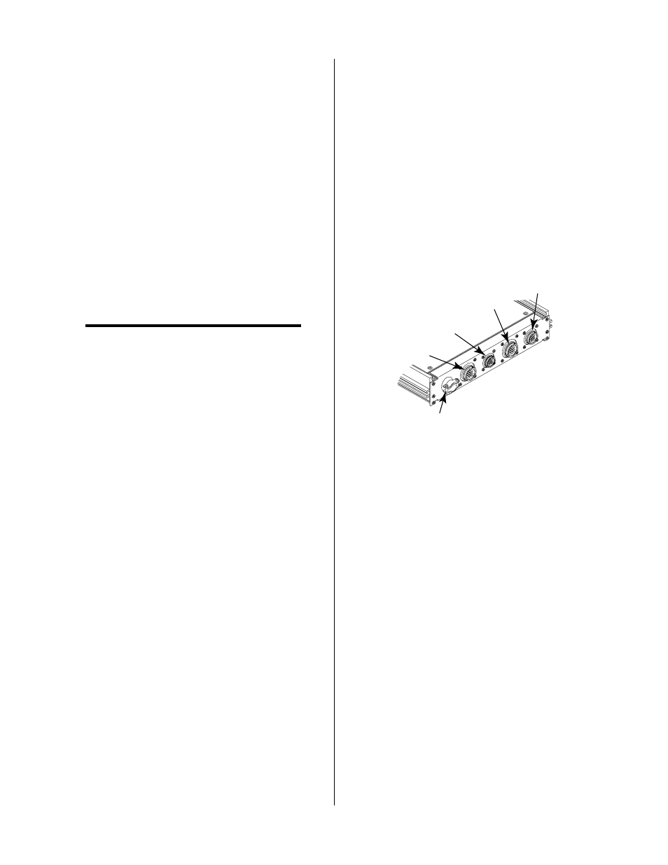
B. Rear Panel
A-01426
1
2
3
4
5
Figure 4-2 Rear Panel Connectors
1. MOTOR (J43) Connector
Connector to interface the Standoff Control to the
lifter motor assembly. Signals include drive (up to
+/-20 vdc), tachometer (0 to +/- 15 vdc) and TORCH
ON WORK switch (NC).
2. PLASMA (J42) Connector
Connector to interface the Standoff Control to the
Plasma Power Supply.
3. EXTERNAL POWER (J41) Connector
Connector to interface the Standoff Control to a re-
mote 48 vdc bias supply.
4. CNC (J40) Connector
Connector to interface the Standoff Control to the
CNC equipment when the interface cable has a mat-
ing connector.
5. Strain Relief
Connection to interface the Standoff Control to the
CNC equipment when there is no mating connector.
The CNC cable is fed through the strain relief and
connected to an internal terminal strip (J11).