Tweco SC11 User Manual
Page 20
INSTALLATION PROCEDURES
3-4
Manual 0-2556
PLA
SM
A O
N
AR
C V
OL
TS
RE
MO
TE
ST
AN
DO
FF
C
ON
TR
OL
T.H
.C. A
CTIV
E
PIE
RC
E
HT (in
che
s)
0.1
0.3
0.4
0.5
0.2
END
OF
CU
T
RETR
AC
T (%
)
0
25
75
100
UP
DN
TOR
CH
TORCH
MO
DE
MODE
LIFT
ER
LIFTER
SPE
ED
SPEED
PIE
RC
E
DEL
AY
(sec)
0.5
1
2
3
0.75
0.25
0.1
AU
TO
HT
FIN
D
HT
HI
LO
A-00689
Screw
Screw
Cover
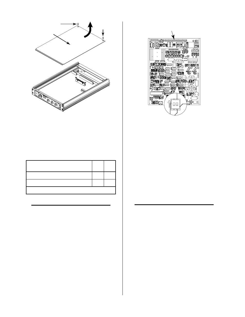
Figure 3-6 Cover Removal
2. Remove the enclosure cover by lifting straight up at
the rear of the cover and pulling it towards the rear of
the unit. The front edge of the cover fits under a lip
on the front panel assembly.
3. Identify internal switch SW1 and confirm that the
switch is set for the desired system as follows:
System
SW1-
1
SW1-
2
Without Motion Signal (OK-To-Move)
ON
ON
With Motion Signal (OK-To-Move)
OFF* OFF*
* = Factory Setting
NOTE
Refer to Section 4.04-E for operation when start-
ing the the cutting operation off the plate (work-
piece).
Standoff Control
PC Board Assembly
A-00861
SW1
Type System
Selection
2
1
ON
Figure 3-7 Switch SW1 Location
B. CNC Interface
Isolated START, standoff inhibit (CSD) and motion
(OK-To-Move) signals are available at the Rear Panel
CNC (J40) connector or an internal terminal strip (J11).
The motion signal (OK-To-Move) may be selected to
be either a contact closure or 24 VAC switched
through the contact. The Standoff Control is factory-
set for 24 VAC operation. The purpose of selecting
24 VAC is to drive a relay coil whose current must
not exceed 150 ma.
NOTE
The 24 VAC may be required by some cutting ma-
chine controllers.