07 installation with automated systems, 08 internal selections – Tweco SC11 User Manual
Page 19
Manual 0-2556
3-3
INSTALLATION PROCEDURES
A-01428
Customer's
Power Source
(120/240 VAC)
External Power
Supply
Standoff Control
SC11
Supplied Input Power Cable
With 120 VAC Plug
Supplied Output Power Cable
Attached to External
Power Supply
Figure 3-5 External Power Supply
3. Connect the end of the output power cable from the
external power supply, to the rear panel of the Stand-
off Control (SC11). Make the connection to the EX-
TERNAL POWER connector (J41).
4. Plug the input power cable into a mating connector
from the customer's power source. If a different type
plug is required do the following:
a. Cut off the 120 VAC plug.
b. Install the correct type plug (customer supplied)
onto the end of the input power cable.
This completes the installation of the external power sup-
ply for the Automated System.
3.08 Internal Selections
A. Switch (SW1) Selection
The Standoff Control Assembly has one internal switch
(SW1) that is used for some plasma cutting systems with-
out an arc transfer or motion signal. Turning ON SW1-1
and SW1-2 will generate the signal as soon as the pilot
arc voltage drops from open circuit to under 195v. This
occurs as soon as pilot is initiated so the PIERCE DELAY
should be used to delay the motion signal. This will al-
low time for arc transfer and piercing.
NOTE
Switch SW1 is not needed for Automated Systems
(Merlin 1000, PakMaster XL Plus or Pak Master
150XL) and both positions should be in the OFF
position.
To check or change the switch selection use the following
procedure:
1. Remove the two cover mounting screws on the top of
the Standoff Accessory.
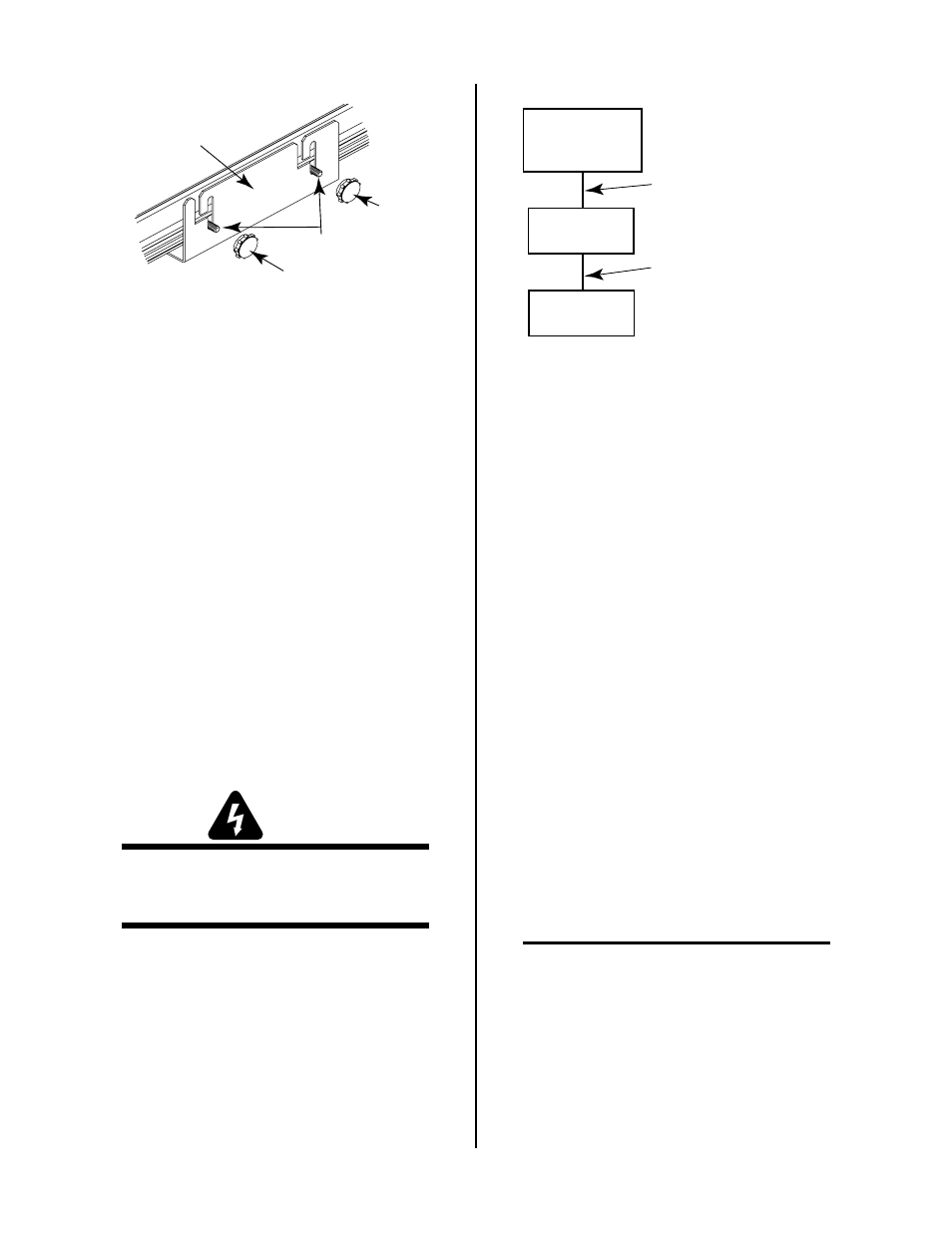
Knob
Hex Head
Bolts
Knob
Mounting Bracket
A-00674
Figure 3-4 Knob Installation
4. Place one knob on each of the bolts protruding from
the bracket slots.
5. The Standoff Control unit can be adjusted for the best
viewing angle. Adjust the viewing angle per the fol-
lowing:
a. Loosen the four knobs sercuring the Standoff Con-
trol to the Mounting Bracket.
b. Adjust the Standoff Control for the desired angle.
c. Tighten all four knobs.
d. If the angle is not correct, loosen knobs, adjust the
unit until the proper viewing angle is found, and
retighten all knobs.
3.07 Installation With Automated
Systems
This Section describes the installation of an external power
supply components to allow use of the Standoff Control
with an Automated Cutting System.
WARNING
Disconnect primary power at the source before as-
sembling or disassembling power supply, torch
parts, or torch and leads assemblies.
1. Locate the external power supply assembly and cables
shipped with the Standoff control.
2. Connect the supplied input power cable , with 120
VAC plug, to the input of the external power supply.