Section 4: operation, 01 introduction, 02 functional overview – Tweco SC11 User Manual
Page 25: 03 operating controls, Section 4, Operation -1, A. front panel, Figure 4-1 front panel operating controls
Manual 0-2556
4-1
OPERATION
SECTION 4:
OPERATION
4.01 Introduction
This Section provides a description of the Standoff Con-
trol Accessory followed by operating procedures.
4.02 Functional Overview
The Standoff Control Accessory extends the necessary sys-
tem controls away from the power supply and is an ac-
cessory with standard machine torch systems.
There is are various connections available at the Rear
Panel of the Standoff Control Accessory. These connec-
tions provide inputs and outputs to allow various parts
of the system to be operated from one station.
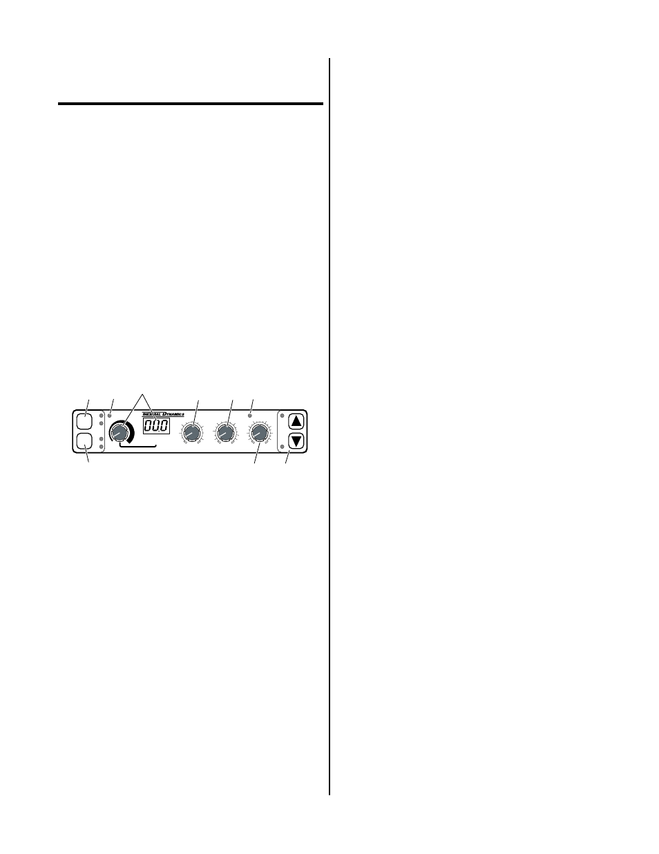
4.03 Operating Controls
A. Front Panel
1
2
3
4
5
6
7
8
A-00691
PLASMA ON
ARC VOLTS
REMOTE STANDOFF CONTROL
T.H.C. ACTIVE
PIERCE
HT (inches)
0.1
0.3
0.4
0.5
0.2
END OF CUT
RETRACT (%)
0
25
75
100
UP
DN
TORCH
TORCH
MODE
MODE
LIFTER
LIFTER
SPEED
SPEED
PIERCE
DELAY (sec)
0.5
1
2
3
0.75
0.25
0.1
AUTO
HT
FIND
HT
HI
LO
9
Figure 4-1 Front Panel Operating Controls
1. MODE Pushbutton and Indicators
The momentary MODE pushbutton switch selects
one of four modes of operation.
• Fully automatic - AUTO HT and FIND HT in-
dicators ON
• Automatic height - AUTO HT indicator ON
and FIND HT indicator OFF
• Find height - AUTO HT indicator OFF and
FIND HT indicators ON
• Fully Manual - AUTO HT and FIND HT indi-
cators OFF
When power is supplied the Standoff Control enters
the fully automatic mode. The AUTO HT and FIND
HT indicators will be ON. Pressing MODE once turns
FIND HT indicator OFF. Pressing MODE again turns
AUTO HT indicator OFF and FIND HT indicator ON.
Pressing MODE a third time turns both indicators
OFF for fully manual mode. Pressing MODE the
forth time returns to fully automatic operation.
2. LIFTER SPEED Pushbutton and Indicators
The momentary LIFTER SPEED pushbutton switch
selects one of two torch lifter speeds.
• High speed - HI indicator ON and LO indicator OFF
• Low speed - LO indicator ON and HI indicator OFF
Pressing the LIFTER SPEED switch toggles between
HI and LO.
When power is supplied the Standoff Control auto-
matically selects the HI Lifter Speed mode. The HI
indicator will be ON. Pressing LIFTER SPEED once
turns HI indicator OFF and LO indicator ON. Press-
ing LIFTER SPEED the thrid time returns to the HI
Lifter Speed mode.
At lower cutting speeds the HI mode may cause os-
cillation or diving toward the work during the cut. If
this happens it is recommended that the operator se-
lect the LO lifter speed.
3. PLASMA ON Indicator
When the Standoff Control sends a start signal to the
Plasma Power Supply the PLASMA ON indicator
turns ON. The start signal is sent automatically after
finding height.
4. ARC VOLTS Control and Display
The ARC VOLTS control allows the operator to se-
lect the desired arc voltage from 65 to 195, as indi-
cated at the ARC VOLTS Display. Volts above 199
will cause the display to indicate over range (left dis-
play digit is "1"). The standoff, distance from torch
to work, may be changed during cutting by chang-
ing the ARC VOLTS setting.
Prior to enabling the PLASMA ON indicator a deci-
mal point will be displayed on the right hand side of
the ARC VOLTS Display indicating preview mode.
After the PLASMA ON indicator is turned ON the
ARC VOLTS Display indicates the actual arc volts
from 0 to 199.
Three decimal points displayed in the ARC VOLTS
Display indicate the Standoff Control is receiving a
standoff inhibit (corner slowdown - CSD) signal.
5. PIERCE HT (inches) Control
The PIERCE HT (height) controls the starting distance
from torch to workpiece from nearly zero to 1/2
inches.