Section 2: introduction & description, 01 scope of manual, 02 general description – Tweco SC11 User Manual
Page 15: 03 specifications & design features, Section 2, Introduction & description -1
Manual 0-2556
2-1
INTRODUCTION & DESCRIPTION
SECTION 2:
INTRODUCTION &
DESCRIPTION
2.01 Scope of Manual
This manual contains descriptions, operating instructions
and maintenance procedures for the SC11 Standoff Con-
trol Accessory. Service of this equipment is restricted to
properly trained personnel; unqualified personnel are
strictly cautioned against attempting repairs or adjust-
ments not covered in this manual, at the risk of voiding
the Warranty.
Read this manual thoroughly. A complete understand-
ing of the characteristics and capabilities of this equip-
ment will assure the dependable operation for which it
was designed.
2.02 General Description
The SC11 Standoff Control Accessory extends the neces-
sary system controls away from the power supply and is
an accessory for use with standard machine torch sys-
tems.
NOTE
The SC11 Standoff Control functions without con-
nection to the Remote Control Accessory RC6010.
The SC11 Standoff Control has all the connections re-
quired at the rear panel. The connections are for CNC
Control, External Power, Lifter Motor, and Plasma Power
Supply. The inputs and outputs at these connections al-
low the various parts of the system to be operated at one
station.
The Standoff Control receives bias power (+48 vdc), torch
voltage signal (0-12 vdc = 0-200 arc volts) and sends and
receives power supply and CNC control signals such as
start, arc transfer (OK-To-Move) and standoff inhibit
(CSD).
The Standoff Control operates the torch lifter motor as-
sembly to find height, regulate height and retract at end
of cut. Height is regulated by comparing the torch arc
voltage with a preset reference voltage (ARC VOLTS con-
trol) and using the resulting error voltage to raise and
lower the torch lifter motor.
A-00686
PLA
SM
A O
N
ARC VOLTS
RE
MO
TE
ST
AN
DO
FF
CO
NT
RO
L
T.H
.C. A
CTIV
E
PIER
CE
HT (i
nche
s)
0.1
0.3
0.4
0.5
0.2
END
OF C
UT
RET
RAC
T (%
)
0
25
75
100
UP
DN
TOR
CH
TORCH
MO
DE
MODE
LIFT
ER
LIFTER
SPE
ED
SPEED
PIER
CE
DEL
AY (s
ec)
0.5
1
2
3
0.75
0.25
0.1
AUTO
HT
FIND
HT
HI
LO
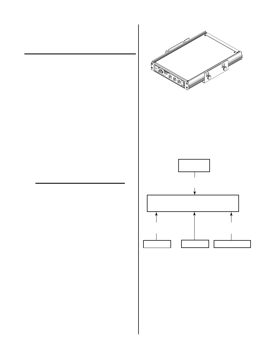
Figure 2-1 SC11 Standoff Control
All necessary cables are supplied for the type system or-
dered. If the SC11 Standoff Control Accessory is not pur-
chased as part of a system, the appropriate remote con-
trol cable and a CNC cable (if required) must be ordered
separately. Some systems may require an external 48 volt
power source. Refer to Section 6, Parts Lists, for order-
ing information.
A-00700
Standoff
Control Accessory
CNC
Lifter Motor
Lifter Motor
Control Cable
Power Supply
Control Cable
Plasma Power
Supply
CNC
Control Cable
Input Power
Figure 2-2 System Configuration With SC11
2.03 Specifications & Design
Features
A. Standoff Control
The following applies to the Standoff Control Assembly
only.
1. System Compatiblility
The Standoff Control Accessory was designed to be
used with various Plasma Cutting Systems