07 servicing machine torch components, 07 servicing machine torch components -7 – Tweco PCM-120 Machine Torch User Manual
Page 37
Manual 0-2698
5-7
CUSTOMER/OPERATOR SERVICE
5. Tighten the threaded locking nut with the flat
(non-chamfered) edge against the torch head, then
loosen the nut slightly by turning it back approxi-
mately one-half turn.
6. Install the torch head on the handle.
NOTE
The torch switch connectors are made to fit into
the matching connectors.
7. Connect the two torch switch leads.
8. Tape the two control cable connector leads to-
gether.
9. Pull the leads sheathing over the connectors and
secure with electrical tape to the torch leads.
10. Roll the torch switch sheath back over the handle.
11. Install torch parts in torch.
12. Align the Torch Control Switch on the handle in
the desired position for cutting, position the torch
head then tighten the threaded locking nut against
the torch handle.
NOTE
There will be a slight gap between the torch head
and the lock nut.
5.07 Servicing Machine Torch
Components
WARNINGS
Disconnect primary power to the system before
disassembling the torch or torch leads.
DO NOT touch any internal torch parts while the
AC indicator light on the front panel of the Power
Supply is ON.
A. Removing Machine Torch Head
1. Remove the shield cup, tip, gas distributor and
electrode from the torch head assembly.
2. Remove shrink on tubing.
3. Locate the tape at the back end of the torch posi-
tioning tube. Remove the tape from the torch
lead sleeving and slide the sleeving back (see
NOTE).
NOTE
The positioning tube will not slide over the torch
lead sleeving.
4. Unscrew the positioning tube from the torch adap-
tor on the torch head assembly and slide the posi-
tioning tube back over the leads.
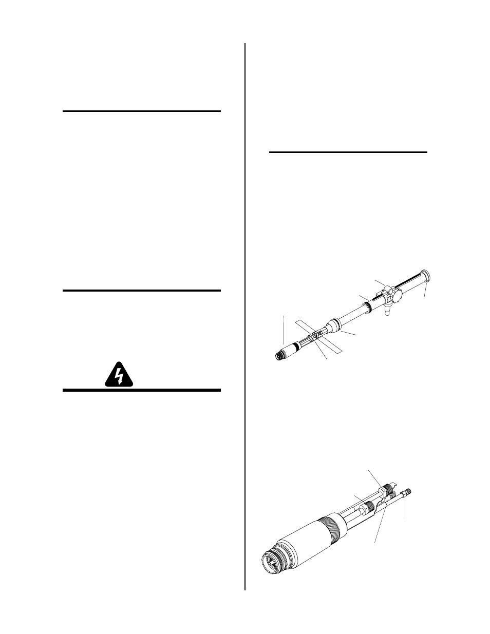
5. Unscrew the torch adaptor from the torch head
assembly. Slide the torch adaptor back over the
leads to expose the plasma (+), secondary, cool-
ant supply (-), and coolant return connectors.
Positioning Tube
Torch Adaptor
Lead Connections
A-00663
Bushing
Pinion Assembly
Machine
Torch Head
Figure 5-7 Torch Mounting Assembly
6. Disconnect the plasma (+), secondary, coolant sup-
ply (-), and coolant return connectors to allow re-
moval of the torch head. Note the location of the
torch leads insulator which separates the nega-
tive and positive leads.
Plasma Lead (+)
Coolant Return Lead
(LH Threads)
Secondary Lead
Coolant (-)
Supply Lead
A-02198
Figure 5-8 Torch Head Removal