06 servicing hand torch components, 06 servicing hand torch components -6 – Tweco PCM-120 Machine Torch User Manual
Page 36
CUSTOMER/OPERATOR SERVICE
5-6
Manual 0-2698
5.06 Servicing Hand Torch
Components
A. Removing Torch Switch and Torch Head
Assembly
Removing the torch control switch assembly requires
gaining access to the switch wiring and partially dis-
assembling the torch handle, per the following pro-
cedure:
1. Remove the shield cup, tip, gas distributor and
electrode from the torch head assembly.
2. Roll the torch switch sheath back over the handle
to expose the tape covering the torch switch con-
nectors.
NOTE
Use a soap and water solution on the sheath to as-
sist in rolling.
Sheath
Connectors From
Torch Switch
Torch Handle
Torch Control
Switch
A-02196
Threaded Locking Nut
Figure 5-5 Torch Control Switch Wiring
3. Carefully cut and remove the tape from the leads
and the end of the leads sheathing.
4. Slide the sheathing back to expose the torch switch
connectors.
5. Remove the tape securing the two connectors to-
gether.
6. Disconnect the torch switch leads.
NOTE
The torch switch connectors are made to fit into
the matching connectors.
7. Remove torch from handle.
NOTE
Keep the lock nut threaded on the torch head.
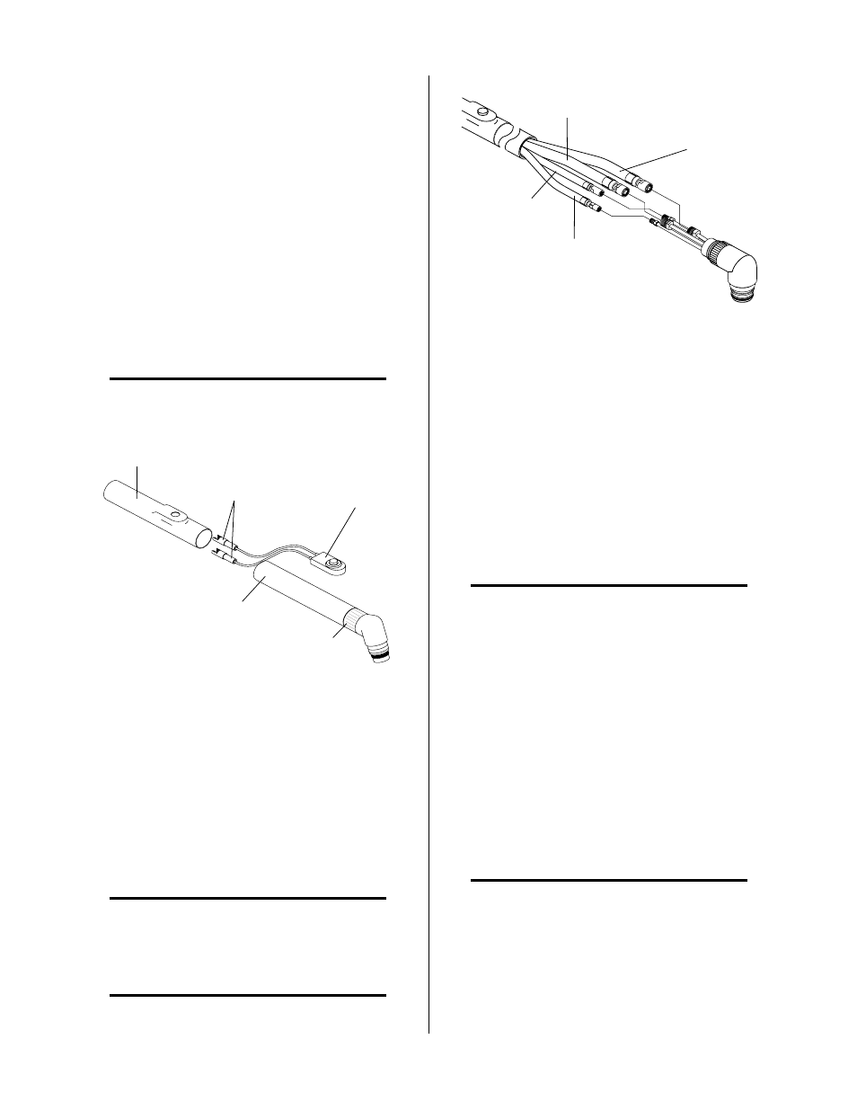
A-02197
Secondary Lead
Plasma (+) Lead
Coolant Return Lead
Coolant (-) Supply Lead
Figure 5-6 Torch Head Removal (PCH-120)
8. Disconnect all four leads to disconnect the torch
head.
9. Remove torch head assembly.
10. Remove the torch handle and switch from the
leads.
11. If the torch switch is defective, remove the switch
from the torch handle.
B. Reassembling Torch Switch and Torch
Head Assembly
NOTE:
Verify that small rubber duck valve is in torch
plasma fitting.
To install the torch switch or torch head assembly use
the following procedure:
1. Slide the torch handle with torch switch and
sheathing over the torch leads.
2. Connect all four leads to connect to the replace-
ment torch head assembly.
3. Remove the rigid insulator from the old Torch
Head Assembly from between the layers of
Estermat paper and install replacement insulator.
Refer to Figure 5-9 for location and orientation of
rigid insulator.
NOTE
Over a period of time there may be a breakdown of
the estermat paper causing the Torch Head to short
out if the rigid insulator is not installed.
4. Secure the rigid insulator in place with electrical
tape.