Section 3: installation procedures, 01 introduction, 02 site location – Tweco PCM-120 Machine Torch User Manual
Page 17: 03 unpacking, 05 connecting torch, Section 3, Installation procedures -1
Manual 0-2698
3-1
INSTALLATION PROCEDURES
SECTION 3:
INSTALLATION
PROCEDURES
3.01 Introduction
This section describes installation of the Torch. These
instructions apply to the Torch and Leads Assemblies
only; installation procedures for the Power Supply, Op-
tions, and Accessories are given in Manuals specifically
provided for those components.
The complete installation consists of:
1. Site Selection
2. Unpacking
3. Setting Up Torch
4. Connecting Torch
5. Gas Connections
6. Operator Training
3.02 Site Location
Select a clean, dry location with good ventilation and ad-
equate working space around all components.
Review the safety precautions in the front of this manual
to be sure that the location meets all safety requirements.
3.03 Unpacking
NOTE
Torches ordered as part of a system are factory as-
sembled to the power supply and are pacckaged in
one shipping carton.
Each component of the system is packaged and protected
with a carton and packing material to prevent damage
during shipping. Components are packaged as follows:
1. Unpack each item and remove all packing material.
2. Locate the packing list(s) and use the list to identify
and account for each item.
3. Inspect each item for possible shipping damage. If
damage is evident, contact your distributor and/or
shipping company before proceeding with system
installation.
3.05 Connecting Torch
WARNING
Disconnect primary power at the source before dis-
assembling the torch or torch leads.
The Torch Leads must be properly installed to the
Power Supply for proper operation. Make all torch
connections to the Torch Bulkhead Panel per the fol-
lowing:
NOTE
Equipment ordered as a system will have the Torch
factory connected to the Power Supply.
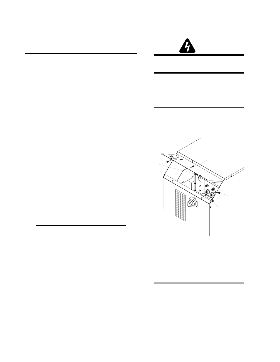
1. Turn the two screw latches securing the front ac-
cess panel to the power supply front panel.
Bulkhead
Access
Panel
Screw
Latches
Torch Leads
Shield Stud
A-02684
Figure 3-2 Power Supply Front Access Panel
2. Lift up on the access panel to gain access to the
torch bulkhead panel.
3. Feed the Control Cable Fitting through the rub-
ber boot in the front panel.
NOTE
For hand torches, the Control Cable Fitting is part
of the torch leads assembly. For machine torches,
the Control Cable Fitting is separate from the torch
and connects to either a Remote Hand Pendant or
a CNC Computer or other device.
4. Feed the end of the torch leads through the rub-
ber boot in the front panel.
5. Connect Control Cable Fitting to Control Cable
Connector.