05 cut quality, 05 cut quality -3 – Tweco PCM-120 Machine Torch User Manual
Page 23
Manual 0-2698
4-3
OPERATION
1. Unscrew and remove the shield cup from the torch
head.
2. Using the multi-purpose wrench (5/8 inch slot) re-
move the tip.
Electrode
Shield Cup
Tip
Gas
Distributor
Torch Head
Water Tube Extension
(Gouging Only)
A-02188
Figure 4-3 Torch Parts
3. Tilt the torch head to remove the gas distributor. The
end of the multi-purpose wrench can be used to help
remove the gas distributor.
4. Using the multi-purpose wrench (electrode area) re-
move the electrode.
5. Remove gouging water extension tube, if used.
6
. Install the desired electrode for the operation into the
torch head. The circular area around the wrench used
for electrodes will also align the electrode in the torch
head. This will prevent installing the electrode on an
angle and cross threading the electrode in the torch
head.
7. Install gouging water extension tube if required.
8. Install the desired gas distributor and tip for the op-
eration into the torch head.
NOTE
Be careful not to overtighten the electrode and tip
when reinstalling.
9. Hand tighten the shield cup until it is seated on the
torch head. If resistance is felt when installing the
cup, check the threads before proceeding.
4.05 Cut Quality
NOTE
Cut quality depends heavily on set-up and param-
eters such as torch standoff, alignment with the
workpiece, cutting speed, gas pressures, and op-
erator ability.
Cut quality requirements differ depending on applica-
tion. For instance, nitride build-up and bevel angle may
be major factors when the surface will be welded after
cutting. Dross-free cutting is important when finish cut
quality is desired to avoid a secondary cleaning opera-
tion. The following cut quality characteristics are illus-
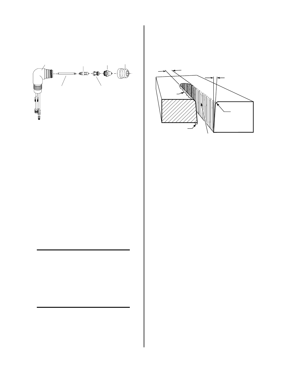
trated in the following Figure:
Kerf Width
Cut Surface
Bevel Angle
Top Edge
Rounding
Cut Surface
Drag Lines
Dross
Build-Up
Top
Spatter
A-00007
Figure 4-4 Cut Quality Characteristics
A. Cut Surface
The desired or specified condition (smooth or rough)
of the face of the cut.
B. Nitride Build-Up
Nitride deposits can be left on the surface of the cut
when nitrogen is present in the plasma gas stream.
These buildups may create difficulties if the material
is to be welded after the cutting process.
C. Bevel Angle
The angle between the surface of the cut edge and a
plane perpendicular to the surface of the plate. A per-
fectly perpendicular cut would result in a 0° bevel
angle.
D. Top-Edge Rounding
Rounding on the top edge of a cut due to wearing
from the initial contact of the plasma arc on the work-
piece.
E. Bottom Dross Build-up
Molten material which is not blown out of the cut
area and re-solidifies on the plate. Excessive dross
may require secondary clean-up operations after cut-
ting.
F. Kerf Width
The width of the cut (or the width of material re-
moved during the cut).