Tweco 6000 Cutting Systems User Manual
Page 36
SERVICE
5-6
Manual 0-2689
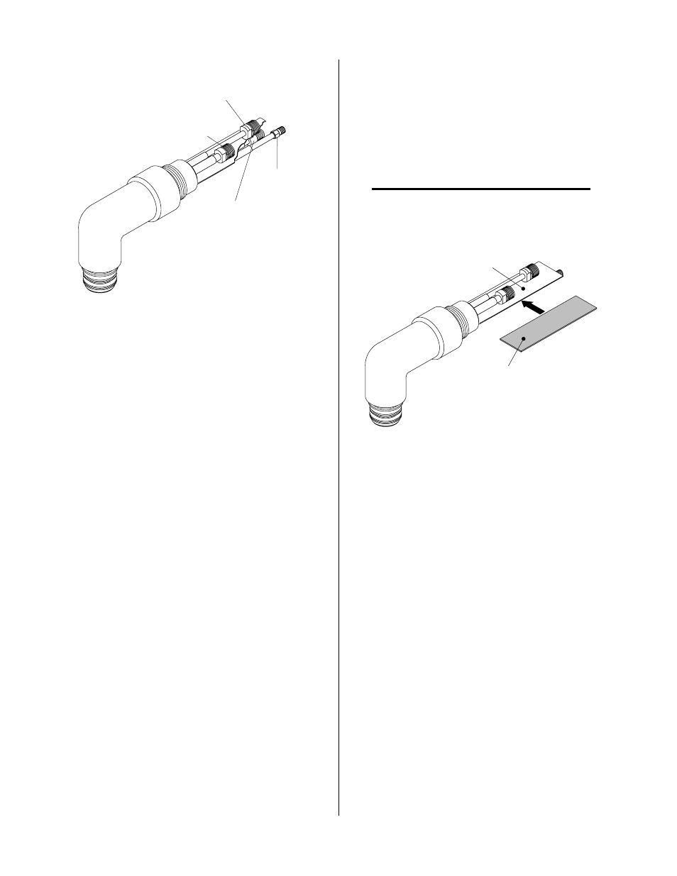
Plasma Lead
Coolant Return (-) Lead
(LH Threads)
Secondary (+)
Lead
Coolant
Supply Lead
A-01989
Figure 5-6 Torch Head Removal
4. Remove the rigid insulator from the old Torch
Head Assembly from between the layers of
estermate paper.
5. Unscrew and remove the torch adapter from the
torch head assembly.
B. Reassembling Machine Torch Assembly
1. Slide the torch adapter down over the leads and
screw the adapter securely onto the back of the
torch head assembly.
2. Slide the rigid insulator between the layers of
estermate paper on the replacement Torch Head
Assembly (see note).
NOTE
Over a period of time there may be a breakdown of
the estermate paper causing the Torch Head to short
out if the rigid insulator is not installed.
Two Layers Of
Estermat Paper
Rigid Torch
Leads Insulator
A-01990
Figure 5-7 Rigid Insulator Installation
3. Secure the rigid insulator in place with electrical
tape.
4. Connect the plasma, secondary (+), coolant sup-
ply, and coolant return (-) connectors.
5. Secure leads and tubing with single layer of elec-
trical tape.
6. Slide the positioning tube down over the leads
and thread it into the torch adapter on the torch
head assembly.
7. Install the front end torch parts.