06 servicing machine torch components, 06 servicing machine torch components -5 – Tweco 6000 Cutting Systems User Manual
Page 35
Manual 0-2689
5-5
SERVICE
2. Current set too low at power supply
a. Increase current setting.
3. Torch is being moved too fast across workpiece
a. Reduce cutting speed (refer to Appendix 2, Cut-
ting Speed Charts).
4. Excessive oil or moisture in torch
a. Hold torch 1/8 inch (3 mm) from clean surface
while purging and observe oil or moisture
buildup (do not activate torch)
F. No gas flow
1. Gas not connected or pressure too low
a. Check source for at least 90 psi (6.2 bar).
2. Faulty components in torch and leads assembly
a. Inspect torch assemblies and replace if neces-
sary. Refer to Section 5.07, Torch and Leads
Troubleshooting.
3. Faulty components in power supply system components
a. Return for repair or have qualified technician
repair per Service Manual.
G. Torch cuts but not adequately
1. Current set too low at power supply
a. Increase current setting
2. Improper plasma or secondary gas selected for applica-
tion
a. Refer to Cut Quality, Section 4.05-H
3. Torch is being moved too fast across workpiece
a. Reduce cutting speed (refer to Appendix 2, Cut-
ting Speed Charts).
4. Excessive oil or moisture in torch
a. Hold torch 1/8 inch (3 mm) from clean surface
while purging and observe oil or moisture
buildup (do not activate torch)
5. Torch tip contacting workpiece
a. Increase standoff distance
6. Torch tip worn
a. Replace tip
7. Incorrect gas pressure
a. Set correct gas pressure
5.06 Servicing Machine Torch
Components
WARNINGS
Disconnect primary power to the system before
disassembling the torch or torch leads.
DO NOT touch any internal torch parts while the
AC indicator light on the front panel of the Power
Supply is ON.
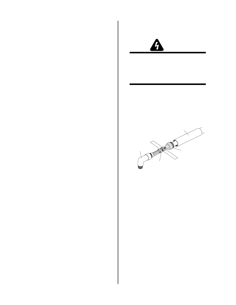
A. Removing Machine Torch Head
1. Remove the shield cup, tip, gas distributor and
electrode from the torch head assembly.
2. Unscrew the positioning tube from the torch
adapter on the torch head assembly and slide the
positioning tube up the leads.
Positioning Tube
Torch Adaptor
Lead Connections
A-01988
Torch Head
Figure 5-5 Torch Mounting Assembly
3. Disconnect the plasma, secondary (+), coolant
supply and coolant return (-) fitting connections.
Note the location of the torch leads insulator
which separates the negative and positive leads.