Section 3: installation, 01 introduction, 02 site location – Tweco 6000 Cutting Systems User Manual
Page 19: 03 unpacking, 04 setting up machine torch, 05 connecting torch, Section 3, Installation -1
Manual 0-2689
3-1
INSTALLATION
SECTION 3:
INSTALLATION
3.01 Introduction
This Section describes installation of the Liquid Cooled
Maximizer 300 Torch. These instructions apply to the
Torch and Leads Assemblies only; installation procedures
for the Power Supply, Options, and Accessories are given
in Manuals specifically provided for those units.
The complete installation consists of:
1. Site Selection
2. Unpacking
3. Setting Up Torch
4. Connecting Torch
5. Gas Connections
6. Operator Training
3.02 Site Location
Select a clean, dry location with good ventilation and ad-
equate working space around all components.
Review the safety precautions in the front of this manual
to be sure that the location meets all safety requirements.
3.03 Unpacking
The product is packaged and protected to prevent dam-
age during shipping.
NOTE
Torch Spare Parts Kits may be packaged for ship-
ment with the Power Supply.
1. Unpack each item and remove all packing mate-
rial.
2. Locate the packing list(s) and use the list to iden-
tify and account for each item.
3. Inspect each item for possible shipping damage.
If damage is evident, contact your distributor
and/or shipping company before proceeding with
system installation.
3.04 Setting Up Machine Torch
WARNING
Disconnect primary power at the source before dis-
assembling the torch or torch leads.
Metal mounting tubes with rack and pinion assemblies
are standard for machine torches.
1. Mount the torch assembly on the cutting table.
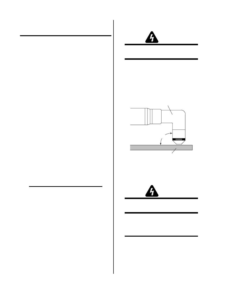
2. To obtain a clean vertical cut, use a square to align
the torch perpendicular to the surface of the work-
piece.
90˚
A-01986
Torch Head
Workpiece
Figure 3-1 Machine Torch Set-Up
3.05 Connecting Torch
WARNING
Disconnect primary power at the source before dis-
assembling the torch or torch leads.
The Torch Leads connect directly to a bulkhead inside
the Arc Starter Box. Connect the Torch Leads per the fol-
lowing procedure:
NOTE
The Arc Starter Box must be installed in the sys-
tem according to the Arc Starter Box Instruction
Manual, 0-2572 supplied with the Arc Starter Box.
1. Remove the cover from the Arc Starter Box if in-
stalled.