Tweco 6000GST Cutting Systems User Manual
Page 66
APPENDIX
A-20
Man
ual 0-2690
APPENDIX 2:
CUTTING SPEED CHAR
TS FOR
MERLIN 6000GST SYSTEMS (contin
ued)
NOTE
If the Optional Secondary Gas/Water Flow Control is used on the Gas Control Module, then the Gas HIGH-FLOW/LOW-FLOW
switch must be in the HIGH-FLOW position.
US Measurements
Argon-Hydrogen Plasma Cutting Data Chart
Maximizer 300 Torch
Stainless Steel
Argon/Hydrogen (H-35) Plasma / Nitrogen Secondary
Electrode
Gas
Distributor
Tip
End Cap
Amperage
Output
Volts
Speed
Standoff
Plasma
Pressure
Plasma
Flowball
Secondary
Pressure
Pierce
Delay
Pierce
Height
inches
Gauge
Cat. No.
Cat. No.
Cat. No.
Cat. No.
amps
vdc
inches/min
inches
psi
psi
seconds
inches
1/2
20-1025
20-0008
20-1032
20-1004
150
165
40
0.188
80
90
45
0.50
0.250
5/8
20-1025
20-0008
20-1032
20-1004
150
165
30
0.188
80
90
45
0.50
0.312
3/4
20-1025
20-0008
20-1032
20-1004
150
170
25
0.188
80
90
45
0.75
0.312
1
20-1025
20-0008
20-1032
20-1004
150
170
20
0.188
80
90
45
1.00
0.312
1 1/4
20-1025
20-0008
20-1032
20-1004
150
175
13
0.188
80
90
45
NR
NR
3/4
20-1025
20-1009
20-1034
20-1005
300
150
40
0.375
90
130
75
0.00
0.500
1
20-1025
20-1009
20-1034
20-1005
300
155
30
0.375
90
130
75
0.25
0.500
1 1/4
20-1025
20-1009
20-1034
20-1005
300
160
22
0.375
90
130
75
NR
NR
1 1/2
20-1025
20-1009
20-1034
20-1005
300
165
15
0.375
90
130
75
NR
NR
1 3/4
20-1025
20-1009
20-1034
20-1005
300
170
12
0.375
90
130
75
NR
NR
2
20-1025
20-1009
20-1034
20-1005
300
175
10
0.375
90
130
75
NR
NR
Material
Thickness
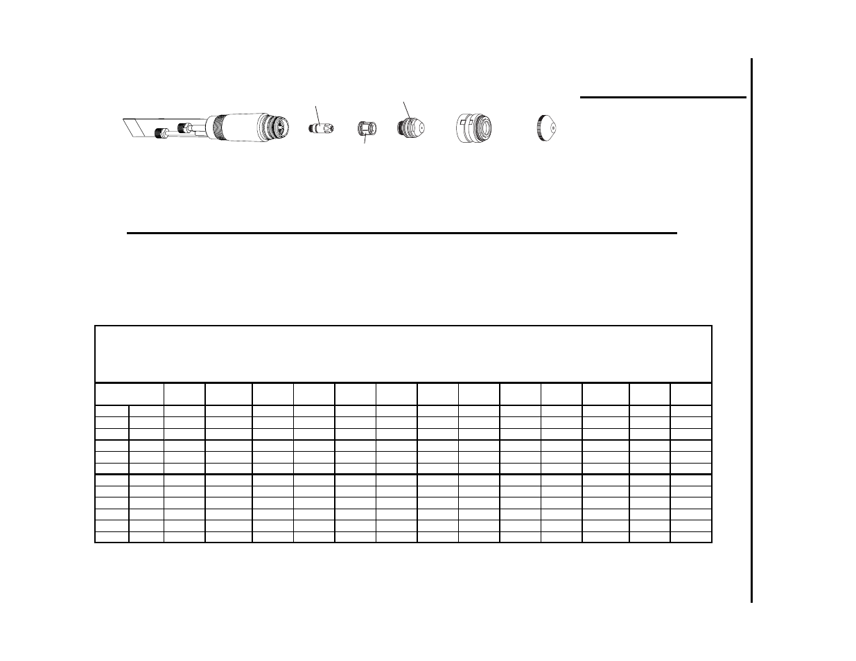
Art # A-02186
Shield Cup Body
20-1002*
End Cap
(See Chart)
Tip
(See Chart)
Gas Distributor
(See Chart)
Electrode
(See Chart)
*or Ohmic Clip
Shield Cup Body 20-1427
Torch Body
180˚: 9-6410
70˚: 9-6457 90˚: 9-6459
NOTE:
If using a torch height control which
offers an ohmic sensing feature, select a
shield cup body with an ohmic clip tab.
Use catalog # 20-1427 for normal cut-
ting and catalog 20-1428 for cutting
underwater.