Triton BRA 200 User Manual
Page 4
6
7
GB
GB
Sandpaper attached to
the face of the batten will
provide grip and support for
the workpiece.
If bevelling small or
awkward pieces on a
regular basis we suggest
you construct a hold-down jig, as shown in
Fig.6, for safer more accurate guidance of the
workpiece.
5. Chamfering (Fig.7)
If you wish to chamfer an
edge, rather than cut a full
bevel, unlock the Bevel
Ripping Guide and move
it to the required position.
Both ends must be locked
at the same selected scale
reading.
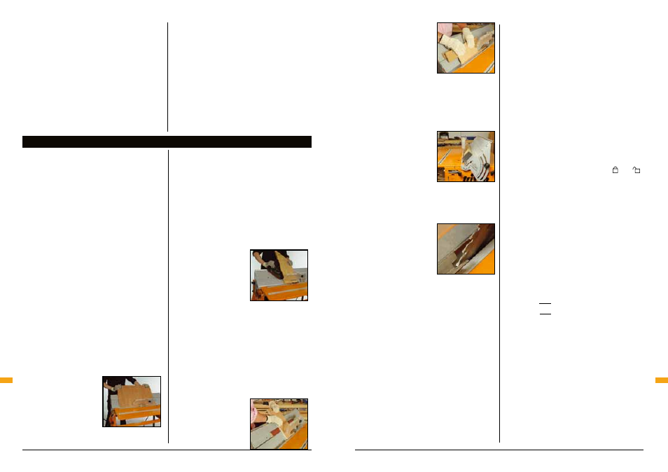
6. Fine Work (Fig.8)
To protect fragile work
from splitting near the end
of the cut, move the front
edge support closer to the
blade, as shown in Fig.8.
This will provide greater
infeed support. After any
adjustment, make sure
the clamping screws are fully tightened. Note:
chamfers are not possible in this position.
7. Compound Mitres
Compound mitre joints require the use of a Series
2000 Workcentre protractor.
Due to the difficulty in calculating the true cutting
angles required for compound mitre joints, the
chart opposite covers some common joints.
For joints not shown on this chart, equations are
provided overleaf for you to calculate the various
cutting angles, using a scientific calculator.
The scales on the Bevel Ripping Guide and
the protractor are calibrated in single degree
increments. While this is suitable for general
work, compound mitres require settings within
the degree increments. Carefully estimated
fractions of a degree will provide the required
results.
Always practice the joints first using scrap
material.
Choose the shape you wish to build, (try the
triangle or square first - they’re the easiest). Then
decide how steep a bevel angle you want, shown
as b° on the chart. (Shallow angles and narrow
boards result in picture frames or trays, larger
angles and wide boards result in planter boxes).
Step 1
Cut each of your workpieces to exactly the same
length in the table saw mode, and cut opposing
MITRE ANGLES (M°) at each end using the
Workcentre protractor. Use the outer scale of
the protractor (45°- 0 - 45°), with the and
symbols indicating which side of “0” to set it.
(If you use the left table slot in table saw mode,
the protractor positions and settings are the
same as those shown in the protractor diagrams.)
Step 2
Fit the Bevel Ripping Guide and set it to the
BEVEL GUIDE ANGLE shown.
Re-cut all of your mitres on the Bevel Ripping
Guide using the protractor positions and settings
shown.
Equations
M°
= tan
-1
( )
B° = cos
-1
(
)
M° = True mitre angle to be cut
B° = True bevel angle (BEVEL GUIDE ANGLE)
m° = Corner half angle
b° = Side angle to be horizontal
sidewards play at the back of your blade, and
check whether your saw is correctly mounted on
the slide chassis.
Storage note: The track arms must be set at 90°
for the quadrants to be folded behind the work
panel for compact storage.
• Most bevel angles can be cut with the
overhead guard in place. If you remove the
guard for a specific cut, take great care and
replace the overhead guard before continuing
with other cuts.
• Keep fingers completely clear of the blade,
including the area behind the workpiece close
to the blade.
• Take care when handling workpieces and off-
cuts, bevel cuts can result in sharp edges.
Assembly / Operating
Operating
OPERATING
Fig.3
Fig.4
Fig.5
Fig.6
Fig.7
It’s a good idea to practice your bevel cuts on
scrap material.
Stand to the left of the Workcentre, hold the
workpiece firmly down onto the front edge
support and against the work panel. As the
back of the workpiece passes off the front edge
support, avoid dipping it down against the blade,
as this will cause a slight step in the bevel. This
is particularly noticeable with shorter pieces,
because of their limited contact with the edge
supports.
By practicing on scrap material, you will find the
best hand positions, and the best use of hold-
down pressure to avoid this final “dip”. Begin by
practicing on larger pieces, and try using either
the top of the work panel, (or the top of one of
the're bates in the panel) as finger rests to help
you control the workpiece throughout the cut.
Preferably use the sandpaper faced batten in
Fig.5, or the protractor, Fig.4, for additional
support.
Note: a perfect bevel requires the workpiece to
have a perfectly straight edge to start with.
1. Wide Workpieces (Fig.3)
The maximum width of
manageable workpiece
partly depends on the
skill and experience of the
operator. As a general rule,
up to 600mm (24") widths
can be handled
quite comfortably.
For larger sizes you should have someone assist
you.
2. Long Workpieces
When bevelling long workpieces, use a Triton
Multi-Stand to provide infeed and outfeed
support for your workpiece, or have someone
assist you.
3. Narrow Workpieces (Fig.4)
The Workcentre protractor,
inserted into the slot along
the top of the Work panel
(A), can be used for extra
guidance and support
when bevel cutting narrow
workpieces.
The protractor should slide smoothly, without
sidewards play along the full length of the slot.
If this is not the case loosen the Philips-head
screws and adjust the width of the slot until the
protractor slider strip fits snugly, then re-tighten.
If necessary spray the slot with a spray lubricant,
such as RP7 or WD40, to improve the protractor
sliding action.
4. Awkward Workpieces (Fig.5 & 6)
When bevelling short or
awkward shaped pieces,
trim a batten out of 12mm
(
1
⁄
2
") material to fit flush
within the recess running
along the work panel.
Fig.8
tan m°
cos b°
sin m°
sin M°