Triton TCB 100 User Manual
Page 8
8
GB
Assembly
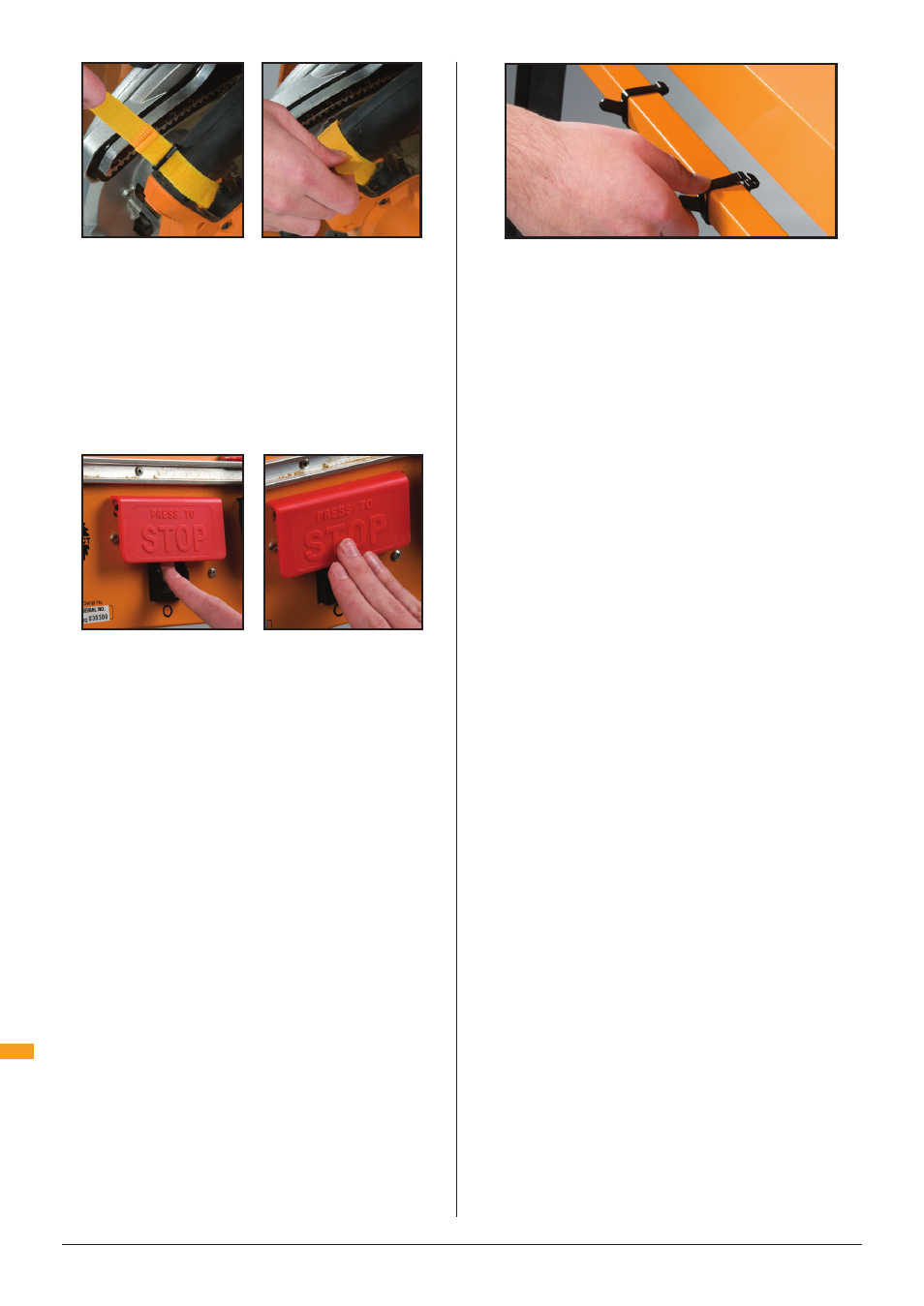
With most saws, the strap can be slid on and off the
saw trigger without having to be undone each time.
CONNECTING THE POWER
Before connecting the power, practice switching on
and off. Do not raise the Stop plate.
Press the green switch with your finger to switch the
power ON. Tap the stop plate with your hand or thigh
to switch OFF (Fig 15).
Make sure the switch is OFF, plug the saw into the
switch box inside the front panel and bring power to
the switch box via an extension cable (min 10 Amp).
Before switching on the power, make sure that nothing
is touching the saw blade, or is likely to vibrate into it,
and that your hands are well clear of the blade.
Switch on and off a few times, with the safety guard
raised approx 25mm above the table, and check that
your saw blade is running true. Any buckle or twist in
the blade will be most evident as the blade is slowing
down to stop. If the blade quivers badly on slow-down,
check whether it is properly seated on the saw arbour.
If it is, for best results you may need to replace your
blade.
FITTING THE STORAGE HOOKS
The Storage Hooks (17) enable temporary storage
of table accessories when not in use. Fit them onto
the left or right hand base tube by opening them and
clipping them around the tube (Fig 16).
THE RIP FENCE
The rip fence can be fitted to the left or right hand
side of the unit, depending on which you find most
comfortable or to suit certain cuts or jigs.
CALIBRATION SETTINGS
The pointer notch is 2.5mm wide, and represents the
kerf (width of cut) of most tungsten carbide tipped
blades. Provided your blade does remove 2.5mm of
material, the scales will be highly accurate with the
fence on either side of the blade.
Always sight down directly from above the notch to
avoid sighting errors.
LOCKING LEVER TENSION
If locking is too firm or too loose, you can vary the
tension of the fence locking levers.
Adjust the Nyloc self-locking nut on the inside of each
end panel.
OUTBOARD SUPPORT
By removing the fence from its tracks and replacing
it upside down, it can be used to provide effective
outboard support when crosscutting larger workpieces
against the protractor.
Secure a batten over the fence arms to create a
surface level with the table. The batten should be
14mm thick, or rebated to 14mm thick.
THE PROTRACTOR
With the sandpaper face forward, away from you,
guide the protractor strip into the slot at the front
panel. Slide the protractor fully along the slot to check
that it slides freely.
The Protractor (6) can be used in trailing mode
(protractor behind the workpiece, Fig 17), or leading
mode (protractor in front of the workpiece, Fig 18).
Trailing mode offers 250mm crosscut capacity,
leading mode 450mm. Use of trailing mode is
recommended unless you require the greater crosscut
capacity.
Fig 15
Fig 14
Fig 15
Fig 16