Assembly – Triton TCB 100 User Manual
Page 5
5
GB
UNPACKING
• Carefully unpack and check that all items are included
and in good condition
• If any items are missing or damaged, do not use this
tool. Return it to your retailer
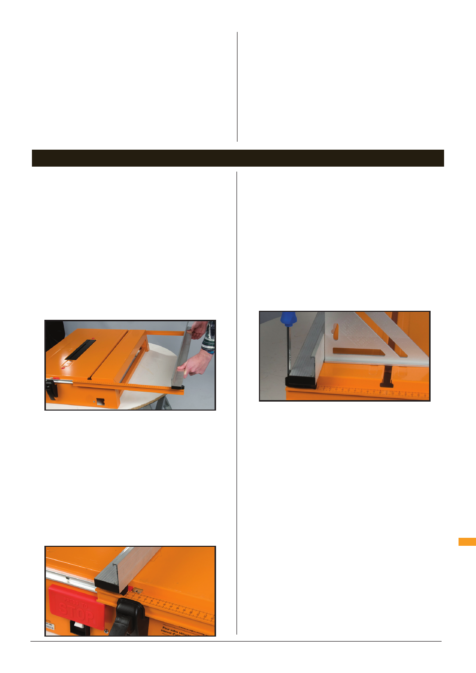
FITTING THE RIP FENCE
Fully raise the Fence Clamp Handles on the end
panels. Unfold the arms of the Rip Fence (D) and slide
it along the fence tracks from the right hand side of
the unit (when viewed from the front panel, which has
the switchbox). Note that the taller part of the fence is
facing the plastic insert in the tabletop (Fig 1).
Study the Fence Scale Pointers. The rip fence can
be fitted on the right or left hand side of the blade,
depending on the cut you are making or your personal
preference.
The 2.5mm calibration notch means that the scales
will be accurate on either side of the blade, provided
your saw has a standard width of cut (kerf) of 2.5mm
Use either side of the notch, depending on which side
your fence is set, to line up with the calibration scales
on the Fence Arms.
NOTE: If your saw has a very thin slitting blade, read
‘Using Thin Blades’ in ‘Troubleshooting’.
With the fence on the right-hand side, align the side
of the notch closest to the fence with the ‘0’ on the
scales (Fig 2). Depress the black plastic fence locking
levers at the front and rear panels to lock the fence in
that position.
Use an accurate set square to check the vertical face
of the rip fence is exactly square to the table at both
ends. If necessary, you can tilt the fence using the
jacking screws (Fig 3).
If you are making any significant adjustments, you will
need to slide the fence clear of the table and loosen or
tighten the pivot bolts attaching the fence arms. The
arms must pivot firmly but freely, without wobbling.
TEMPORARY SAW FITTING
Turn the Main Body (A) upside down and rest it on a
table or bench, with the fence overhanging the edge.
Alternatively, place the unit on wooden packers thick
enough to allow your saw blade, at maximum depth of
cut, to fit through the slot in the table.
With your saw disconnected from power, lock the
blade at full depth of cut and check that the blade is
set at 0° on the saw’s angle adjuster.
Pull back the saw’s safety guard and, with the front of
the saw facing the switch box, lower the blade through
the slot.
NOTE: The slot is sized for a 235mm (9 ¼”) blade. If
you have a smaller saw, slide it backwards until the
back of the blade is approx 10mm from the rear end
of the slot. If your blade does not fit the slot, refer to
‘Troubleshooting – Saw Fitting Problems’.
Choose the four keyhole slots which provide the
best clamping positions for your saw. If you have a
choice of slots, select those that are as far apart as
possible lengthways along the base plate. Try to avoid
e) Maintain power tools. Check for misalignment or
binding of moving parts, breakage of parts and
any other condition that may affect the power
tool’s operation. If damaged, have the power tool
repaired before use. Many accidents are caused by
poorly maintained power tools.
f) Keep cutting tools sharp and clean. Properly
maintained cutting tools with sharp cutting edges are
less likely to bind and are easier to control.
g) Use the power tool, accessories and tool bits etc.
in accordance with these instructions, taking into
account the working conditions and the work to
be performed. Use of the power tool for operations
different from those intended could result in a
hazardous situation.
5) Service
a) Have your power tool serviced by a qualified repair
person using only identical replacement parts.
This will ensure that the safety of the power tool is
maintained.
General Safety Instructions / Assembly
Fig 1
ASSEMBLY
Fig 2
Fig 3