tekmar 664 Snow Detector & Melting Control Installation User Manual
Page 19
19 of 36
©
2009 D
664
-
07/09
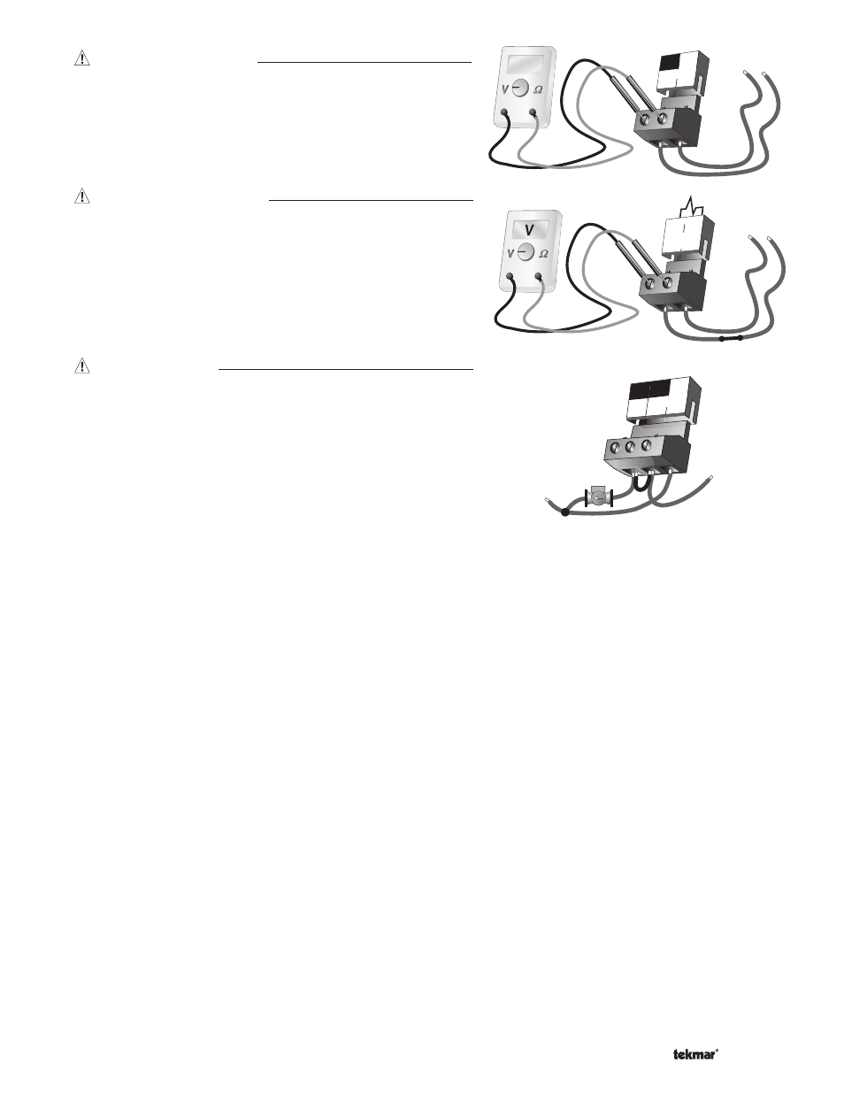
Test The Power Supply
Make sure exposed wires and bare terminals are not in contact with
other wires or grounded surfaces. Turn on the power and measure
the voltage between the Power L and Power N terminals (29 and 30)
using an AC voltmeter, the reading should be between 103.5 and
126.5 V (ac).
Test The Powered Inputs
Melt / Idle Demand
If a melt / idle demand is used, measure the voltage between the
Melt / Idle Demand terminals (19 and 20). When the melting or idling
device calls for heat, you should measure between 20 and 260 V (ac)
at the terminals. When the melting or idling device is off, you should
measure less than 5 V (ac).
Test The Outputs
System Pump (Sys P1)
If a system pump is connected to the Sys P1 terminal (28), make sure
that power to the terminal block is off and install a jumper between the
Sys P1 and Power L terminals (28 and 29). When power is applied
to the Power L and Power N terminals (29 and 30), the system
pump should start. If the pump does not turn on, check the wiring
between the terminal block and pump and refer to any installation
or troubleshooting information supplied with the pump. If the pump
operates properly, disconnect the power and remove the jumper.
Zone Pump or Zone Valve
If a zone pump or zone valve is connected to the Com Zn and Zn 1 terminals (26 and 25), make sure power to the pump or valve
circuit is off and install a jumper between the Com Zn and Zn 1 terminals (26 and 25). When the circuit is powered up, the zone
pump should turn on or the valve should open completely. If no response occurs, check the wiring between the terminal and the
pump or valve and refer to any installation or troubleshooting information supplied with these devices. If a zone pump or zone
valve is connected to the Com Zn and Zn 2 terminals (26 and 27), follow a similar procedure as described for the zone 1 relay.
Stage 1 and 2
If the boiler circuit is connected to the Stage 1 terminals (21 and 22) and / or Stage 2 terminals (23 and 24), make sure power
to the boiler circuit is off, and install a jumper between the terminals. When the boiler circuit is powered up, the boiler should
fi re. If the boiler does not turn on, refer to any installation or troubleshooting information supplied with the boiler. (The boiler may
have a fl ow switch that prevents fi ring until the boiler pump is running). If the boiler operates properly, disconnect the power and
remove the jumper.
Variable Speed Injection Pump
If a variable speed injection pump circuit is connected to the Pwr Mix and Opn / Var terminals (4 and 3), make sure the power
to the terminal block is off and install a jumper between the Pwr Mix and Opn / Var terminals (4 and 3). When the variable speed
pump circuit is powered up, the variable speed pump should operate at full speed. If the pump does not operate, check the wiring
between the terminal block and the pump and refer to any installation or troubleshooting information supplied with the pump. If
the pump operates properly, disconnect the power and remove the jumper.
Mixing Valve Actuator
If a floating action actuating motor circuit is connected to the Pwr Mix, Opn / Var and Cls terminals (4, 3 and 5), make sure
power to the motor circuit is off and install a jumper between the Pwr Mix and Opn / Var terminals (4 and 3). When the circuit
is powered up, the actuator should move in the opening direction. If it does not, check the wiring between the terminals and
the actuating motor. Refer to any installation or troubleshooting information supplied with the motor. If the motor closes instead
of opening, the wiring of the actuating motor must be reversed. If the valve opens correctly, turn off the power to the circuit
and remove the jumper. Install a jumper between the Pwr Mix and Cls terminals (4 and 5). When the circuit is powered up, the
actuator should move in the closing direction. If it does not, check the wiring between the terminals and the actuating motor.
Refer to any installation or troubleshooting information supplied with the motor. If the motor closes correctly, turn off the power
to the circuit and remove the jumper.
30
Power
29
V
103.5 to 126.5 V (ac)
N
L
20 to 260 V (ac)
20
19
Melt/Idle
Demand
28 29
30
Sys
P1
Power
N
L
115 V (ac)
N
L