tekmar 664 Snow Detector & Melting Control Installation User Manual
Page 18
18 of 36
©
2009 D
664
-
07/09
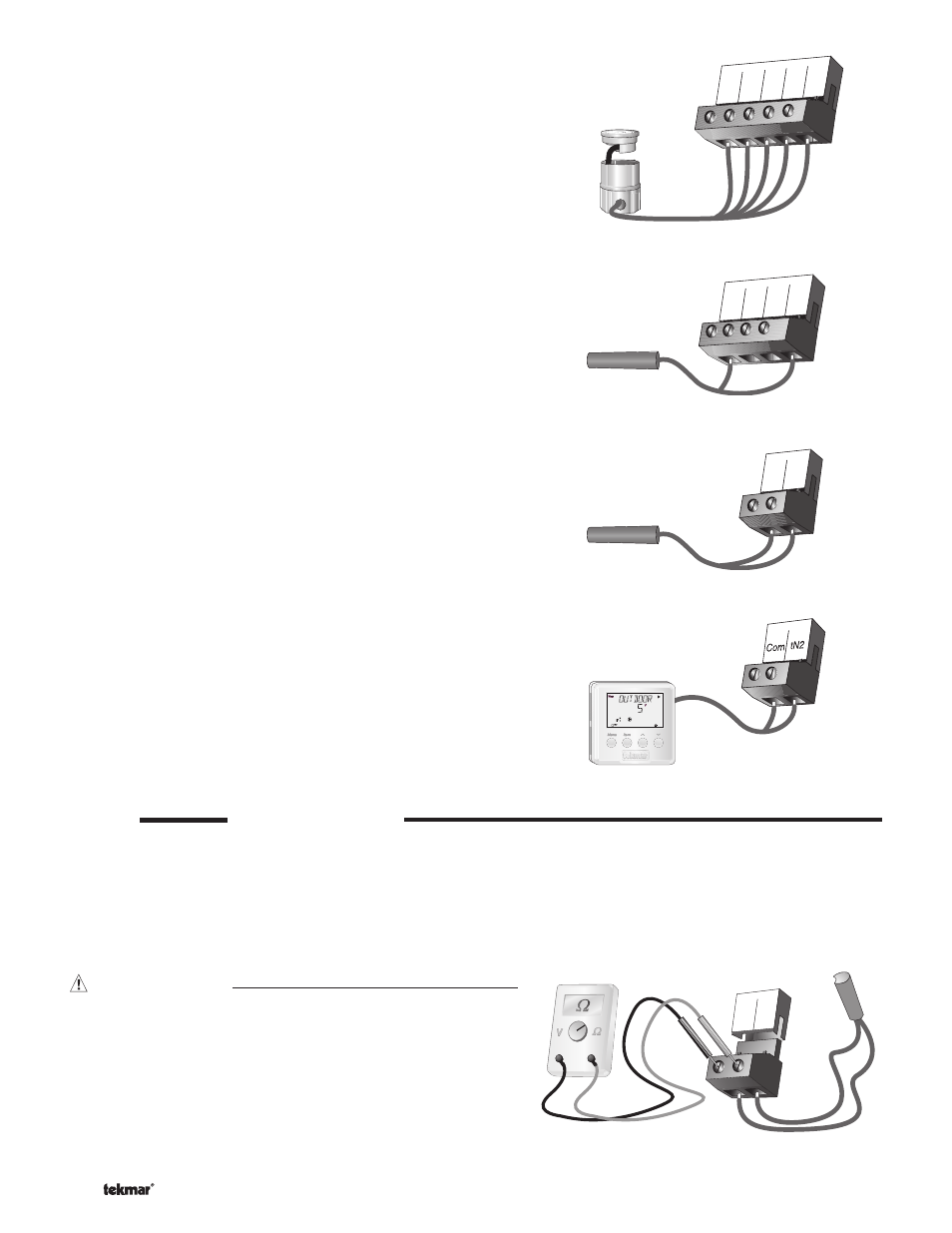
EITHER: Snow / Ice Sensor 090 (Zone 1)
If a Snow / Ice Sensor 090 is used, connect the red wire from the
sensor cable to the Red terminal (6), connect the black wire from the
sensor cable to the Blk / Com terminal (7), connect the blue wire from
the sensor cable to the Blu terminal (8), connect the yellow wire from
the sensor cable to the Yel terminal (9) and connect the brown wire
from the sensor cable to the Brn / Slab1 terminal (10). The snow / ice
sensor is used by the 664 to measure the slab surface temperature
of zone 1. This sensor must be installed fl ush with the slab surface
and 1/2 way between the heating pipes. See Data Brochure D 090
for installation instructions regarding the Snow / Ice Sensor 090 and
Sensor Socket 091.
OR: Slab Sensor (Zone 1)
If a Snow / Ice Sensor 090 is not used for zone 1, a slab sensor
can be used. If a slab sensor is used, connect the two wires from
the slab sensor to the Blk / Com and Brn / SLAB 1 terminals (7
and 10). The slab sensor is used by the 664 to measure the slab
temperature of zone 1.
Note: Proper sensor placement is critical for correct operation of the
664 control. The slab sensor must be installed 1/2 way between the
heating pipes and 1’’ (25 mm) below the surface of the slab. Although
the sensor can be installed directly into the slab, we recommend that
the sensor be installed in tubing or conduit in such a manner that the
sensor can be removed and replaced in case of failure.
Slab Sensor (Zone 2 )
If a slab sensor is used, connect the two wires from the slab sensor
to the Slab 2 and Com terminals (11 and 12). The slab sensor is used
by the 664 to measure the slab temperature of zone 2.
tekmar Net™ (tN2) Device
A Remote Display Module (RDM) 040 or Remote Start / Stop
Module 039 can be connected to the tekmar Net™ (tN2) input.
Connect the Com terminal from the appropriate tN2 device to the
Com terminal (12) on the 664. Connect the tN2 terminal from the
appropriate tN2 device to the tN2 terminal (13) on the 664.
Note: The wires from the RDM and Remote Start / Stop Module are
polarity sensitive. The tN2 device does not operate correctly if the
wires are reversed.
6
Red
7
Blk/
Com
8
Blu
9
Yel
10
Brn/
Slab1
8
7
9
10
Blk/
Com
Blu Yel
Brn/
Slab1
11
Slab
2
12
Com
12 13
STEP FIVE
TESTING THE WIRING
Each terminal block must be unplugged from its header on the control before power is applied for testing. To remove the terminal
block, pull straight down from the control.
The following tests are to be performed using standard testing practices and procedures and should only be carried out by properly
trained and experienced persons.
A good quality electrical test meter, capable of reading from at least 0 – 300 V (ac) and at least 0 – 2,000,000 Ω, is essential to
properly test the wiring and sensors.
Test The Sensors
In order to test the sensors, the actual temperature at each sensor
location must be measured. A good quality digital thermometer with
a surface temperature probe is recommended for ease of use and
accuracy. Where a digital thermometer is not available, a spare sensor
can be strapped alongside the one to be tested and the readings
compared. Test the sensors according to the instructions in the Data
Brochure D 070.
17
Boil
16
Com
OR