Mixing valve actuator, Boiler sensor, Mixing supply sensor – tekmar 664 Snow Detector & Melting Control Installation User Manual
Page 17: Mixing return sensor, 20 ma device
17 of 36
©
2009 D
664
-
07/09
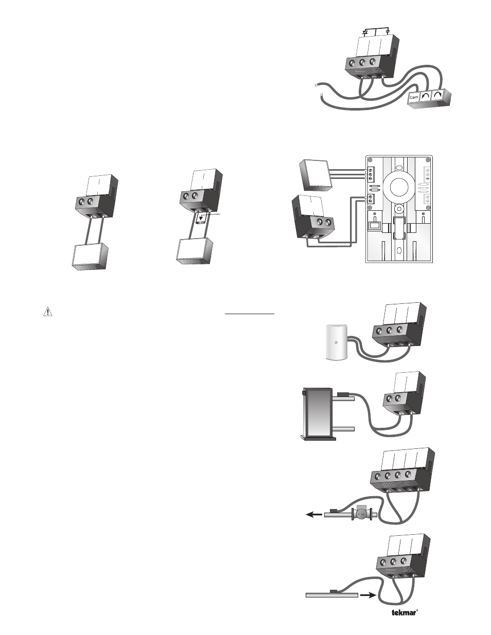
Mixing Valve Actuator
If a mixing valve is used, connect one side of the 24 V (ac) power to
the Pwr Mix terminal (4) on the control. The output relay Opn / Var
(3) is then connected to the open terminal of the actuating motor
and the output relay Cls (5) is connected to the close terminal of the
actuating motor. Connect the second side of the 24 V (ac) circuit to
the common terminal of the actuating motor.
3
Opn/
Var
4
Pwr
Mix
5
Cls
24 to 115 V (ac)
R
C
Connection to Operate
a 4 - 20 mA Device
1 2
+
+
–
–
4-20 mA
Actuating Motor
4-20 mA
500Ω resistor
4-20 mA converted
to 2-10 Vdc output
OR
250Ω resistor
4-20 mA converted
to 1-5 Vdc output
Converting the 4-20 mA
Output to Operate a
1-5 Vdc or 2-10 Vdc Device
1
+
2
–
4 - 20 mA
+
–
0-10 Vdc
Actuating Motor
Sensor and Unpowered Input Connections
Do not apply power to these terminals as this will damage the
control.
Outdoor Sensor
Connect the two wires from the Outdoor Sensor 070 to the Com and
Out terminals (16 and 18). The outdoor sensor is used by the 664 to
measure the outdoor air temperature.
Boiler Sensor
Connect the two wires from the Boiler Sensor 082 to the Com and
Boil terminals (16 and 17). The boiler sensor is used by the 664 to
measure the water temperature of the boiler.
Mixing Supply Sensor
Connect the two wires from the Mixing Supply Sensor 082 to the
Com and Mix Sup terminals (12 and 15). The mixing supply sensor
is used by the 664 to measure the fl uid supply temperature after the
mixing device. Normally the sensor is attached downstream of the
mixing pump.
Mixing Return Sensor
Connect the two wires from the Mixing Return Sensor 082 to the
Com and Mix Ret terminals (12 and 14). The mixing return sensor
is used by the 664 to measure the fl uid return temperature from the
snow melting slab.
16
Com
17
Boil
18
Out
16 17
Boil
Com
Boiler
Sensor
12
Com
13
tN2
14
Mix
Ret
Mix Return
Sensor
13
tN2
14
Mix
Ret
15
Mix
Sup
12
Com
Mix Supply
Sensor
System
Pump
4-20 mA Device
If a 4-20 mA device is used, connect the positive 4-20 mA lead to the 4-20 mA + terminal (1) and the negative 4–20 mA
lead to the 4-20 mA – terminal (2). Maximum resistance allowed in the 4-20 mA circuit is 1000 Ω. The 4-20 mA output can
be converted to either a 2-10 V (dc) or 1-5 V (dc) output by connecting resistor(s). A 0-135 Ω Converter 005 can be used to
convert the 4-20 mA signal to 0-135 Ω.
Modutrol IV
tekmar
B
R
W
+
-
tekmar
V9055
+
-
B
R
W
B
R
W
1
4-20 mA
+
–
2
Converting the 4-20 mA
Output to Operate a
0-135 Ω Actuating Motor