Display and indicator lights operation, Testing the control functions, Testing the control functions step seven – tekmar 661 Snow Detector & Melting Control User Manual
Page 6: Operational test of control functions
6
Display and Indicator Lights Operation
Testing the Control Functions
Step Seven
Operational test of control functions
Slab
Target Slab
% Output
Usage (hours)
Time Remaining
Slab
Target Slab
% Output
Usage (hours)
Time Remaining
Slab
Target Slab
% Output
Usage (hours)
Time Remaining
Slab
Target Slab
% Output
Usage (hours)
Time Remaining
Slab
Target Slab
% Output
Usage (hours)
Time Remaining
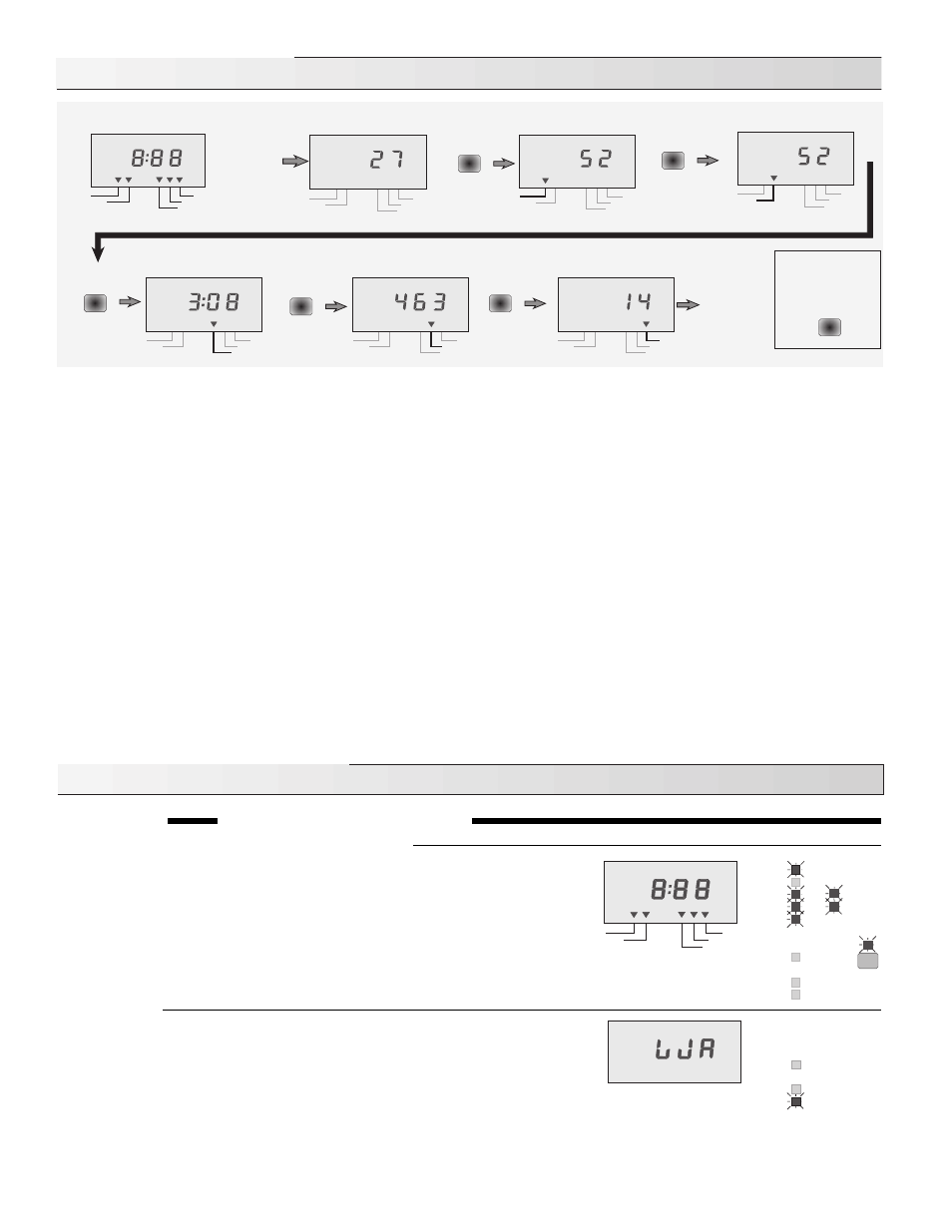
After
power-up,
the control
displays the
“OUTSIDE”
temperature
Press and
release the
item button to
scroll through
the displays
again
POWER-UP DISPLAY
OUTSIDE TEMPERATURE
SLAB TEMPERATURE
Slab
°
F
OUTSIDE
°
F
°
C
OUTSIDE
Slab
Target Slab
% Output
Usage (hours)
Time Remaining
Target Slab
% Output
Usage (hours)
Time Remaining
°
F
TARGET SLAB TEMP.
TIME REMAINING
HOURS OF USE
% HEAT OUTPUT
°
F
Item
Press and
Release the
item button
Item
Press and
Release the
item button
Item
Press and
Release the
item button
Item
Press and
Release the
item button
Item
Press and
Release the
item button
Press and hold
the item button for
at least 1 second
to switch between
°
F and
°
C
Item
Indicator lights
Power light on
•
The 120 V ac power supply is connected and the control energized.
Remote light on
•
The remote enable input is
activated.
WWCO light on
•
The control is in Warm Weather Cut Off.
CWCO light on
•
The control is in Cold Weather Cut Off.
Melting light on
•
The system is in Melting Mode.
Idling light on
•
The system is in Idling Mode.
Water light on
•
The Snow/Ice Sensor 090 is detecting the presence of water.
Pump light on
•
The Pump relay is on.
Heat light on
•
The Heat relay is on.
Test light on
•
The control is proceeding through the programmed test routine.
Warning light on
•
The Warning relay is on.
LCD display, indicator lights and Snow/Ice Sensor
When the test button is pressed, the red status lights and LCD segments are
turned on for 7 seconds. The current to the Snow/Ice Sensor’s internal
heater is then increased and if the temperature at the centre of the sensor
does not rise at least 2
°
F in 42 seconds, a warning and error message is
given. If the centre of the sensor is hotter than 120
°
F or the outdoor
temperature is below -5
°
F, the control skips this part of the test. During the
42 seconds the control continues with the remainder of the test sequence.
Warning on
The Warning relay and light turn on and the LCD shows "W A" to indicate that
the Warning device is being tested. If the external warning device does not
activate, the wiring from the control should be checked and the warning
device examined for possible faults. After 10 seconds, the Warning light and
relay are turned off and the test continues.
Note: The test routine can be halted at this, or any of the following steps, by pushing the Test button once. If this is done, the "Test"
light flashes and the control is held in a pause mode for 5 minutes after which time it automatically exits the test routine. Pushing
the Test button during the 5 minute pause allows the control to resume the test routine at the next step.
Pump
Heat
Warning
Power
Remote
Pump
Heat
Warning
CWCO
Melting
Idling
WWCO
Water
Test
°
F
°
C
OUTSIDE
Slab
Target Slab
% Output
Usage (hours)
Time Remaining
• Slab - This is the present surface temperature of the slab as measure by the Snow/Ice Sensor.
• Target Slab - This is the temperature the control wants to achieve i.e. the “Melting” or “Idling” dial setting.
• Time Remaining - When the control is in melting mode and the slab has reached the temperature set by the "Melting" dial, a timer
starts. This display indicates the hours and minutes remaining until the Minimum On Time is reached. The melting system continues
operating after the Minimum On Time is reached if water is still detected.
• Usage - The control displays the total number of hours the heat relay has been on. The upper three digits of the number are displayed
first followed by the lower three digits, followed by a pause.
Example: the control flashes 001 then 298 then pause. The hours of use are therefore 001,298
• % Output - The control varies the amount of heat applied to the snow melt system by cycling the heat relay on and off. This display
indicates the percentage of time the heat relay is on.