Settings, Step six – tekmar 661 Snow Detector & Melting Control User Manual
Page 5
5
Settings
Step Six
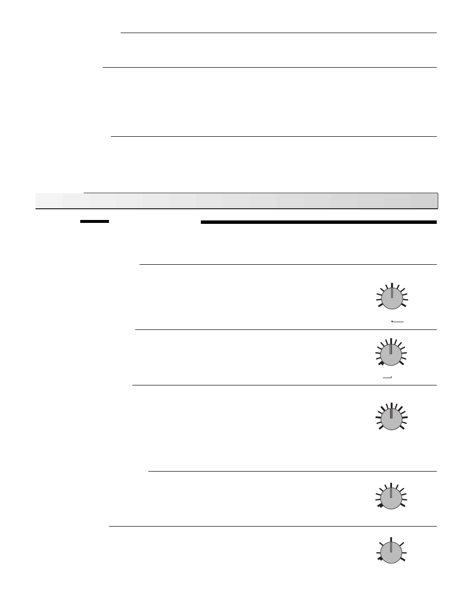
Essential control settings
Before adjusting the dial settings, read through the sequence of operation to ensure that you understand how the control oper-
ates. The dials are factory set at the midpoint of each setting. This reflects typical settings for most systems and is therefore a
good starting point.
Sensitivity
50 %
20
80
Melting
Surface
39
°
F
34
44
Melting Surface Temperature
The “Melting” dial setting is the desired slab surface temperature when the control is in melting
mode and is also used as the WWCO temperature. The “Melting” temperature is usually set based
on local weather conditions. In some areas, heavy snow fall can load a slab at temperatures well
above freezing; in these areas the dial should be set higher. If the melting system response is
sluggish, increasing the “Melting” dial setting may cause the system to melt faster, however, it is
important to remember that increasing this setting generally increases energy consumption.
Idling Surface Temperature
The “Idling” dial setting is based on the requirements of the user. If minimizing the time required
for the slab to reach melting temperature is important then the dial is set slightly below freezing
(<32
°
F). If black ice or frost formation is a concern, the dial is set slightly above freezing (>32
°
F).
It is important to remember that increasing this dial setting increases energy consumption. “Idling”
can also be set to “Off”.
Idling
29
°
F
Off
35
24
Surface
Water detection sensitivity
The sensitivity of the Snow/Ice Sensor to water can be adjusted using the “Sensitivity” dial. As
snow becomes contaminated with dirt, and as the sensor surface itself becomes dirty, the control
may incorrectly indicate the presence of water. If this condition occurs, clean the surface of the
sensor and/or turn down the sensitivity setting. If the snow and rain in the area is very clean, the
sensitivity setting may need to be increased before snow is detected.
Minimum On Time
The Minimum On Time setting is primarily used to ensure a minimum operating time regardless
of the Snow/Ice Sensor reading. The built in timer starts counting down once the slab has reached
the “Melting” temperature. If water is detected after the Minimum On Time has elapsed, the control
continues in melting mode until water is no longer detected by the Snow/Ice Sensor.
CWCO (Cold Weather Cut Off)
The “CWCO” temperature is the coldest temperature at which the melting system operates. This
dial is set based on the melting capabilities of the snow melt system and the economics of melting
snow in extreme conditions.
CWCO
0
°
F
-20
25
Off
Min. On Time
2 hrs
4 hrs
Off
0.5
Note: The Snow/Ice Sensor is installed in a hostile environment and should be cleaned on a regular
basis with a wire brush. After cleaning, check operation by pressing the test button to cycle
the control through the test routine.
Test the power supply
• Make sure exposed wiring or terminals are not grounded or in contact with other wires. Turn on the 120 V ac power and,
using an AC voltmeter, you should measure between 110 and 130 V ac at the
Power N – L (5 and 6) terminals.
Test the Outputs
• If a device is connected to the
Melt terminals (1 and 2), make sure power to the device is off and install a jumper between
terminals 1 and 2. When the device is powered-up, it should operate. If it does not turn on, check the wiring from the terminal
plug to the device and refer to any installation or troubleshooting information supplied with the device. If the device is
operating properly, disconnect the power and remove the jumper.
• Repeat this procedure for any devices connected to the
Warning terminals (3 and 4), Pump terminals (7 and 8) and Heat
terminals (9 and 10).
Connect the control
• Turn the power off and make sure all test jumpers have been removed from the plugs.
• Connect the plugs to the control by carefully aligning them with their respective headers and pushing them upwards. The plugs
should snap firmly into the headers.
• Install the supplied safety dividers between the different voltage wiring chambers. Apply power to the control.
• The control is now ready for operation.