Sequence of operation – tekmar 661 Snow Detector & Melting Control User Manual
Page 2
2
IMPORTANT NOTE:
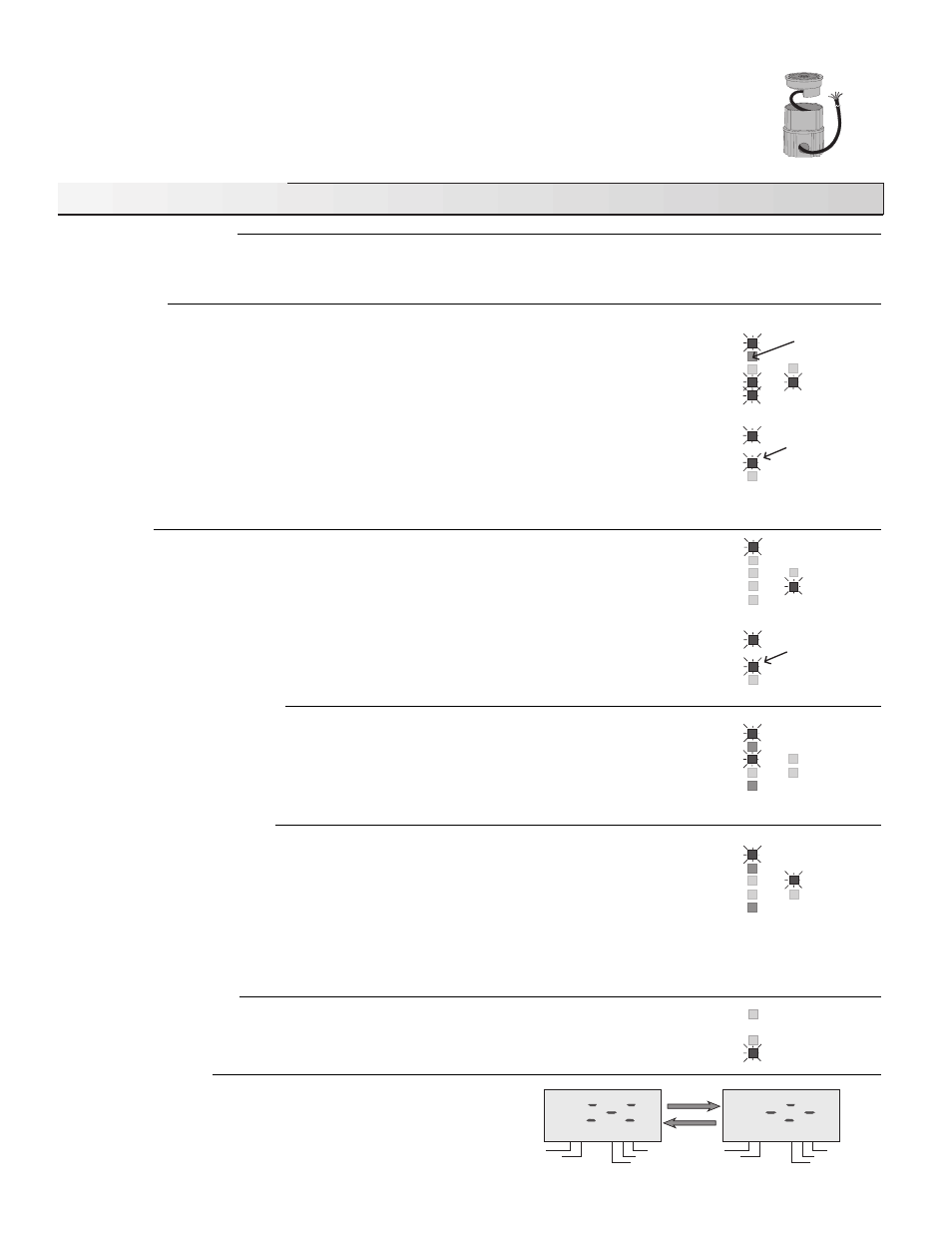
This control requires a Snow/Ice Sensor 090 and Sensor Socket 091. The Snow/Ice Sensor 090 is usually installed
prior to the installation of the control. The installer or designer should plan far enough ahead to allow ample time
for ordering and delivery. The Application Brochures A 661 provide a series of schematics which can be used with
this control. It is important that these applications together with the sequence of operation provided below are fully
understood in order to ensure that the control selected is compatible with its intended use.
Power
Remote
Pump
Heat
Warning
CWCO
Melting
Idling
WWCO
Water
The heat light
cycles on and off
The remote light is
on if a remote enable
signal is present
Power
Remote
Pump
Heat
Warning
CWCO
Melting
Idling
WWCO
Water
The heat light
cycles on and off
Power
Remote
CWCO
Melting
Idling
WWCO
Water
Power
Remote
CWCO
Melting
Idling
WWCO
Water
Sequence of Operation
Slab
Target Slab
% Output
Usage (hours)
Time Remaining
Slab
Target Slab
% Output
Usage (hours)
Time Remaining
Pump
Heat
Warning
Powering up the control
After the Snow Detector & Melting Control 661 is powered up, the red status lights and the LCD segments are turned on for 7 seconds.
The control then displays the “OUTSIDE” temperature.
Melting Mode
Operation using a Snow/ Ice Sensor 090 - The control continually monitors the Snow/Ice Sensor 090.
When snow, ice or water is detected the water light turns on. If the control is not in WWCO or CWCO
(see below for an explanation of these terms), melting mode begins.
Operation using a Remote Enable - Melting mode can also be initiated if a remote enable signal is
present (terminals Com Sen and Rem Sen shorted together) and the control is not in WWCO or CWCO.
The remote enable is typically used with multiple Snow Melting Controls and Snow/Ice Sensors. It can
also be used to manually turn the melting system on by wiring a switch between the remote terminals.
Once the control is in melting mode, the Pump and Melting lights and the Pump and Melt relays are turned
on for at least the Minimum On Time set by the Min. On Time dial. The Heat relay is cycled on and off
to maintain the slab surface at the “Melting” temperature. The method used to cycle the heat relay is called
Pulse Width Modulation (PWM). More information on PWM is provided in Essay 000.
Idling Mode
When the melting system starts from a cold temperature, the time required for the slab to reach "Melting"
temperature can be excessive. To decrease this start up time, the slab can be maintained at an “Idling”
temperature until melting is required. The Idling feature is also useful for preventing frost and light ice
formation. When the control is in idling mode, control operation is similar to melting mode except the
"Melting" light is off and the "Idling" light is on.
Warm Weather Cut Off (WWCO)
The 661 control can operate with or without an Outdoor Sensor 070. If an outdoor sensor is not used, the
control measures the “Outdoor” temperature using the Edge Sensor on the Snow/Ice Sensor 090. If the
“Slab” and “Outdoor” temperatures rise above the “Melting” temperature, the control shuts down the
melting system and enters Warm Weather Cut Off mode. The control remains in WWCO until the “Outdoor”
temperature drops below the “Melting” temperature. The control then continues with normal operation.
Cold Weather Cut Off (CWCO)
Maintaining the slab at a “Melting” or “Idling” temperature in extremely cold weather can be expensive and
may even be impossible. When it does snow at these colder temperatures, the snow is usually dry, light
and less slippery. The control therefore turns the melting system off when the “Outdoor” temperature
(measured using either the Outdoor Sensor 070 or the 090 Edge Sensor) drops below the “CWCO”
setting. The heater in the Snow/Ice Sensor 090 is kept on during CWCO until the control detects snow.
If snow is detected, the heater is turned off but the control retains the snow detected information. When
the “Outdoor” temperature rises above the “CWCO” temperature, the control exits CWCO and continues
with normal operation.
Warning Light and Relay
If a sensor fault occurs, the warning relay and light are turned on and an error message is given. The
lookup table provided on page 7 can be used to determine which sensor has the fault.
Exercising the pump
To prevent the pump from seizing during long WWCO periods, the
Pump relay is turned on for 20 seconds after every 3 days of no
operation. During exercising, the LCD screen alternates between two
special characters as illustrated in the diagram.