tekmar 356 Mixing Control User Manual
Page 9
Copyright © D 356 -0
9/08
9 of 16
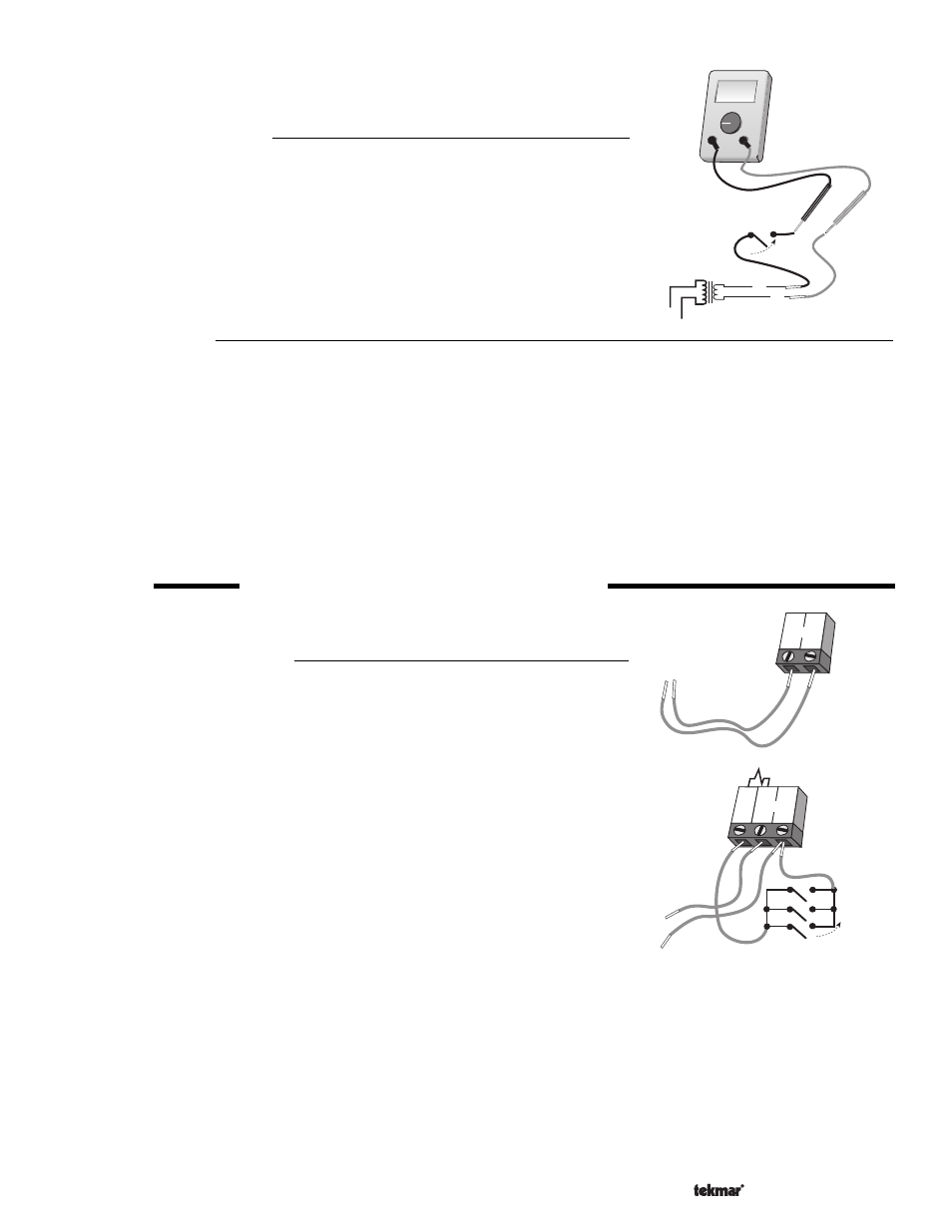
Test The Powered Inputs
Mixing Demand
Measure the voltage between the mixing demand wire and the power wire that goes
to R+ of the control. The voltmeter should read between 22 and 26 V (ac) when the
mixing demand device calls for heat.
Test The Outputs
Boiler
Make sure power to the boiler circuit is off and short the boiler wires. When the boiler circuit is powered up, the boiler should fire.
If the boiler does not turn on, refer to any installation or troubleshooting information supplied with the boiler. (The boiler may have
a flow switch that prevents firing until the boiler loop pump is running). If the boiler operates properly, remove power from the
boiler circuit.
Variable Speed Injection Pump
Short the variable speed injection pump wires and power up the pump curcuit; the variable speed pump should operate at full
speed. If the pump does not operate, check the wiring, and refer to any installation or troubleshooting information supplied with
the pump. If the pump operates properly, remove the power from the variable speed injection pump circuit.
STEP FIVE
ELECTRICAL CONNECTIONS TO THE CONTROL
The installer should test to confirm that no voltage is present at any of the wires.
Powered Input Connections
24 V (ac) Power
Connect the 24 V (ac) power supply to the
Power R+ and Power C- terminals (8 and
9). This connection provides power to the microprocessor and display of the control.
Mixing Demand
To generate a mixing demand, terminal
T(7) must be connected to terminal C-(9)
through a switching device.
24 V (ac)
Class II
Transformer
C
R
Ω
V
V
Mixing demand
switch
24 V (ac)
C-
Power
R+
8
9
C-
T
Power
R+
7
8
9
Mixing demand switches
24 V (ac)