Dip switch setting, Output connections boiler contact, Variable speed injection pump – tekmar 356 Mixing Control User Manual
Page 10: Sensor and unpowered input connections, Outdoor sensor, Boiler sensor, Mixing sensor, Advanced / installer
Copyright © D 356 -0
9/08
10 of 16
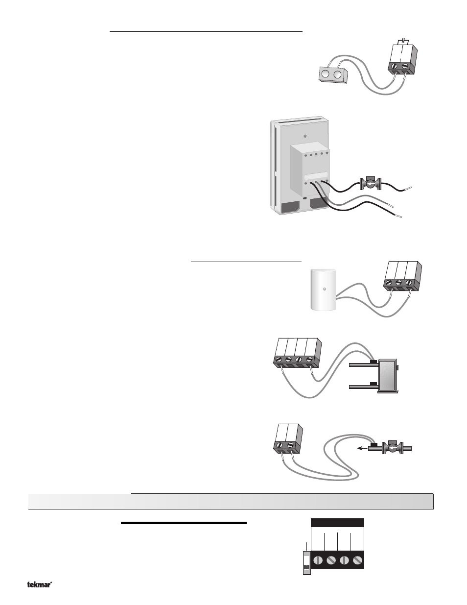
Output Connections
Boiler Contact
The
Boiler terminals (5 and 6) are an isolated output in the 356. There is no power
available on these terminals from the control. These terminals are to be used as a
switch to either make or break the boiler circuit. When the 356 requires the boiler to
fire, it closes the contact between terminals 5 and 6.
Variable Speed Injection Pump
The 356 can vary the speed of a permanent capacitor, impedance
protected, or equivalent pump motor that has a locked rotor current
of less than 2.4 A. Most small wet rotor circulators are suitable as
described in Essay E 021. The 356 has an internal overload pro-
tection circuit which is rated at 2.5 A 250 V (ac). Contact your tekmar
sales representative for details on the repair procedures if this cir-
cuit is blown.
Connect one of the wires from the variable speed injection pump to
one of the black wires from the back of the control. Connect the
second black wire from the back to the live (L) side of the 120 V
(ac) power source. The other wire on the variable speed injection
pump must be connected to the neutral (N) side of the 120 V (ac)
power supply. Connect the green wire on the back of the control to
ground.
Sensor and Unpowered Input Connections
Do not apply power to these terminals as this will damage the control.
Outdoor Sensor
Connect the two wires from the Outdoor Sensor 070 to the
Com and Out terminals (1
and 3). The outdoor sensor is used by the 356 to measure the outdoor air tempera-
ture.
Boiler Sensor
Connect the two wires from the Boiler Sensor 071 to the
Com and
Boil terminals (1 and 4). The boiler sensor is used by the 356 to
measure the boiler temperature.
Mixing Sensor
Connect the two wires from the Mixing Sensor 071 to the
Com and
Sup terminals (1 and 2). The mixing sensor is used by the 356 to
measure the supply water temperature after the variable speed
injection pump. Normally the sensor is attached to the pipe down-
stream of the system pump.
DIP Switch Setting
ADVANCED / INSTALLER
The
Advanced / Installer DIP switch is used to select which items are
available to be viewed and / or adjusted in the user interface.
T
T
T
T
Boiler
5
6
STOP
Refer se
rvicing to
qualified
personnel. O
pening vo
ids
warranty
.
Ground
(green)
Pump
(black)
120 V or L
(black)
N
Sup
Out
2
3
Com
1
Boiler return
sensor
or
Boiler supply
sensor
Boil
Sup Out
2
3
4
Com
1
Mixing
sensor
Sup
Com
1
2
System
pump
Inst/Adv
Do not apply power
Com Sup Out Boil
1
2
3
4