Minimum modulation, Example, Maximum modulation – tekmar 270 Boiler Control User Manual
Page 6: Modulation, Motor speed
©
2010 D
270
-
08/10
6
of
24
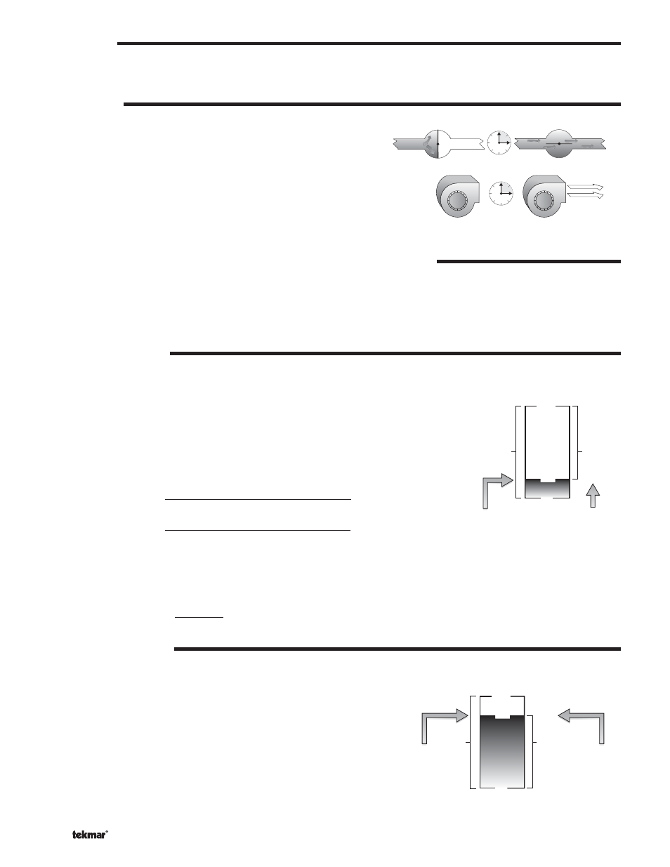
The Motor Speed is the amount of time the boiler requires to go from 0%
modulation to 100% modulation.
Gas valve actuating motors have a design time from fully closed to
fully open which can be found in the manufacturer’s manual. The
Motor Speed
should be set to this time.
The Motor Speed setting for a Variable Frequency Drive (VFD) is the
amount of time required to go from a stopped position to 100% fan
speed. Since a VFD has a very quick response rate, it may be necessary
to increase the Motor Speed setting in order to increase the stability of
the boiler modulation.
MODULATION RANGE (0 to 10 V (dc), 2 to 10 V (dc), 0 to 20 mA, 4 to 20 mA)
The modulation output can be adjusted from a 0 to 10 V (dc) or to a 2 to 10 V (dc) output range using the Boil Modulation setting.
If a 0 to 20 mA range is required, set the Boil Modulation item to 0 to 10 V (dc) and cut the jumper wire located next to the modulation
output.
If a 4 to 20 mA range is required, set the Boil Modulation item to 2 to 10 V (dc) and cut the jumper wired located next to the
modulation output.
MINIMUM MODULATION
MAXIMUM MODULATION
88%
0%
2 V (dc)
2 V (dc)
100%
10 V (dc)
9 V (dc)
Control's
Output
Signal
Range
Maximum
Modulation
Boiler's
Maximum
Input Signal
Boiler's
Input
Signal
Range
The minimum modulation defines the minimum output signal from the control to the boiler
burner. It is based on a percentage of the control’s output signal range.
The Minimum Modulation setting for boilers with power burners is typically set to
0%.
For boilers with electronic operators, the boiler’s input signal range may not match the
output signal range of the 270 control. The Minimum Modulation setting limits the control
output range in order to match the boiler’s input range.
To calculate the Minimum Modulation, use the following formula:
For 0 to 10 V (dc):
Minimum Modulation =
0 V (dc) – Boiler’s Minimum Input Signal
0 – 10 V (dc)
x 100%
For 2 to 10 V (dc):
Minimum Modulation =
2 V (dc) – Boiler’s Minimum Input Signal
2 – 10 V (dc)
x 100%
Example:
A boiler requires a 1.8 V (dc) signal to fire the boiler at low fire. The boiler can be modulated to 10 V (dc) where it reaches high fire. This
means the boiler’s input signal range is 1.8 to 10 V (dc). The 270 control has an output signal range of 0 to 20 mA.
To make the two signal ranges the same, the Minimum Modulation required is:
Minimum Modulation =
0 V – 1.8 V
0 V – 10 V
x 100% = 18%
MAXIMUM MODULATION
MINIMUM MODULATION
18%
0%
0 V (dc)
1.8 V (dc)
100%
10 V (dc)
10 V (dc)
Control's
Output
Signal
Range
Minimum
Modulation
Boiler's Minimum
Input Signal
Boiler's
Input
Signal
Range
The maximum modulation defines the maximum output signal from the control
to the boiler burner. It is based on a percentage of the control’s output signal
range.
The Maximum Modulation setting for boilers with power burners is
typically set to 100%.
For boilers with electronic operators, the boiler’s input signal range may not
match the output signal range of the 270 control. The Maximum Modulation
setting limits the control output range in order to match the boiler’s input
range.
MODULATION
The Boiler Control 270 provides a modulating output signal to operate a single modulating boiler. The control first closes the boiler
contact on to ignite the ignition sequence. The boiler is then modulated from the minimum modulation using Proportional, Integral
and Derivative (PID) logic in order to satisfy the boiler target temperature.
MOTOR SPEED