Cleaning the control, Dip switch settings, Connecting the control – tekmar 270 Boiler Control User Manual
Page 17: Test the modulating output, General, Advanced / installer, Off / exercise
17 of 24
© 2010 D 270 - 08/10
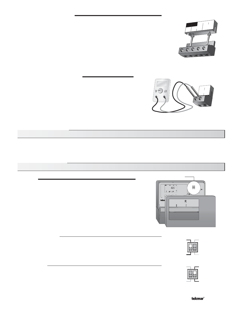
CONNECTING THE CONTROL
Make sure all power to the devices and terminal blocks is off, and remove any remaining
jumpers from the terminals.
Reconnect the terminal blocks to the control by carefully aligning them with their respective
headers on the control, and then pushing the terminal blocks into the headers. The terminal
blocks should snap firmly into place.
Install the supplied safety dividers between the unpowered sensor inputs and the powered
or 115 V (ac) wiring chambers.
Apply power to the control. The operation of the control on power up is described in the
Sequence of Operation section of the brochure.
TEST THE MODULATING OUTPUT
If a modulating device is used, connect an ammeter to the modulating
output Mod V (dc) terminals (11 and 12) and observe the current reading
during operation. For example, when using a 0 to 10 V (dc) output, the
initial percentage output is zero and the meter should read 0 V (dc). As
the Boiler Modulation in the VIEW menu increases, the meter reading
should increase until the Boiler Modulation reaches 100% at which point
the meter should read 10 V (dc). When the 0 to 10 V (dc) modulation
decreases, the meter should start at 10 V (dc) and eventually reach
0 V (dc) when the display shows 0% Boiler Modulation.
6 7
4
8
Prim
P1
L
N
DHW
Pmp/Vlv
Power
5
V
12
11
ModV(dc)
-
+
Cleaning the Control
The control’s exterior can be cleaned using a damp cloth. Moisten the cloth with water and wring out prior to wiping control. Do not
use solvents or cleaning solutions.
DIP Switch Settings
GENERAL
The DIP switch settings on the control are very important and should be set
to the appropriate settings prior to making any adjustments to the control
through the User Interface. The DIP switch settings change the items that
are available to be viewed and / or adjusted in the User Interface.
If a DIP switch is changed while the control is powered up, the control responds
to the change in setting by returning the display to the VIEW menu.
Advanced / Installer
The Advanced / Installer DIP switch selects the access level of the control. In the
Installer
access level, a limited number of items may be viewed and / or adjusted. In the
Advanced
access level, all items may be viewed and / or adjusted.
Off / Exercise
The Off / Exercise DIP switch selects whether or not the control is to exercise the primary
pump and boiler pumps. If the DIP switch is set to Exercise, the pumps are operated for
10 seconds after every three days of inactivity.
DIP Switches
Test
Test
Boiler Control 270
One Modulating Boiler & DHW
Menu
Item
Boiler Demand
DHW Demand
Modulation
DHW Priority Override
off
not testing
red
testing
red
testing paused
Made in Canada by
tekmar Control Systems Ltd.
Power
115 V ±10% 50/60 Hz 600 VA
Relays
230 V (ac) 5 A 1/3 hp, pilot duty 240 VA
Demands
20 to 260 V (ac) 2 VA
Signal wiring must be rated at least 300 V.
For maximum heat
press & hold Test
button for 3 seconds.
Meets Class B:
Canadian ICES
FCC Part 15
D
at
e C
od
e
Advanced
Off
Installer
Exercise
Advanced
Off
Installer
Exercise
Advanced
Off
Installer
Exercise